
Cobot EOAT Machining: Inertia & RFQ Guide
Plan cobot EOAT machining with payload and inertia calculations, contact-edge risk checks, flange tolerances, and an RFQ checklist. Request a CAD/DFM review.
Published and reviewed: November 4, 2026. Scope: global, English-language engineering and procurement guidance for CNC machined collaborative robot end-of-arm tooling (EOAT), adapter plates, and brackets; dimensions use SI units. This guide helps buyers screen a design and prepare an RFQ. The worked examples are reproducible arithmetic, not measured robot performance or safety certification. The integrator must confirm the applicable standard editions, local requirements, robot model, software version, and completed cell risk assessment before release.
Cobot EOAT machining starts with the complete carried assembly: gripper, adapter, quick changer, sensors, fasteners, and the heaviest workpiece. Check mass, center of gravity (CoG), inertia about the relevant axes, and accessible contact geometry before removing material. A lighter tool with a long overhang can demand more acceleration torque than a heavier compact assembly.
Catalog payload alone cannot establish a workable cycle. Protective stops may involve incorrect payload settings, collisions, cable forces, acceleration, mounting conditions, or other causes. A machining change can address mass distribution and geometry; it cannot by itself authorize higher speed or prove a collaborative application safe.
Decision Summary:
- Screen inertia by axis: For a parallel-axis comparison, the offset contribution is
m × d², wheredis perpendicular to the rotation axis. A 5 kg mass at 260 mm contributes 0.338 kg·m², versus 0.0392 kg·m² for 8 kg at 70 mm. These exclude each assembly's own CoG inertia. - Pocket selectively: Remove material from low-stress regions while retaining bolt load paths, thread engagement, seal lands, and ribs. Weight reduction requires stiffness and fatigue checks.
- Specify contact geometry without a compliance shortcut: Rounded edges and recessed fasteners can reduce contact hazards. A 2 mm radius is a possible drawing choice, not a universal ISO/TS 15066 minimum or a safe-speed approval.
- Match the actual flange drawing: Verify the pilot, dowel, bolt pattern, fasteners, and finished fits against the selected robot and any intermediate quick changer.
For tooling teams preparing production drawings or prototype cell components, request an engineering DFM and quotation review with your 3D STEP models, target cobot arm model code, operating cycle accelerations, and payload center-of-gravity targets.
For drawing preparation and finishing specifications, consult our EOAT machining tolerance and surface-finish guide and material selection guide for robot grippers.
1. The Dynamic Payload Trap: Static Mass vs. Rotational Moment of Inertia
For a simplified single-axis screening model, joint torque includes gravity and angular acceleration demand:
τ ≈ m × g × L + J × α
Here m is carried mass in kg, g ≈ 9.81 m/s², L is the perpendicular gravity moment arm in meters, J is inertia about the selected axis in kg·m², and α is angular acceleration in rad/s². Torque is in N·m. This estimate omits multi-axis coupling, friction, and controller behavior; it is not a robot sizing or stopping model.
The Parallel Axis Theorem (Steiner's Law)
The parallel axis theorem relates inertia about two parallel axes:
J_axis = J_CoG + m × d²
J_CoG is the inertia about the parallel axis through the component CoG; d is the perpendicular distance to the axis being evaluated. Moving a 1.5 kg manifold from 50 mm to 150 mm perpendicular offset increases only its offset contribution ninefold, from 0.00375 to 0.03375 kg·m². Axial distance along the tool Z axis does not automatically increase inertia about that same axis; it can increase inertia about transverse axes.
Illustrative comparison: same transverse axis; CoG inertia excluded
A: 6.0 kg × (0.065 m)² = 0.02535 kg·m²
B: 4.5 kg × (0.250 m)² = 0.28125 kg·m²
B / A = 11.09 times the offset contribution
No speed, protective-stop outcome, or torque margin is established.
For a complete assembly, calculate its combined CoG using r_CoG = Σ(m_i × r_i) / Σm_i, with all coordinates in one declared flange frame. Rotate component inertia tensors into aligned axes before combining them. Keep separate empty, loaded, and alternative-jaw configurations. Do not confuse inertia about the flange with inertia about the combined CoG when exporting controller data.
Table 1: Reproducible Offset-Inertia Screening Examples
These hypothetical inputs illustrate mass distribution, not manufacturer ratings. Every row uses J_offset = m × d², ignores self-inertia, and assumes a distance perpendicular to the same selected axis.
| Screening case | Mass (kg) | Perpendicular offset (m) | Offset contribution (kg·m²) | Procurement implication |
|---|---|---|---|---|
| Compact complete tool | 6.0 | 0.065 | 0.02535 | Confirm all purchased components are included |
| Extended lighter tool | 4.5 | 0.250 | 0.28125 | Review overhang before choosing a larger robot |
| Manifold near selected axis | 1.5 | 0.050 | 0.00375 | Compare routing and service access |
| Same manifold farther away | 1.5 | 0.150 | 0.03375 | Offset term is nine times greater |
| Long light assembly | 5.0 | 0.260 | 0.33800 | Request a shorter alternative concept |
| Short heavier assembly | 8.0 | 0.070 | 0.03920 | Mass still needs its own payload check |
For model-specific approval, obtain the current payload/CoG envelope and inertia guidance from the robot manufacturer. Universal Robots' higher-payload application guide illustrates why tool orientation and the applicable payload curve matter. Its UR10e example is not an envelope for other robots.
2. ISO/TS 15066: Contact Edge Radii and Pressure Control
ISO/TS 15066:2016 addresses collaborative industrial robot systems and their work environment, supplementing ISO 10218 guidance. For a Power and Force Limiting (PFL) application, the integrator must evaluate foreseeable contact involving the robot, EOAT, held part, fixtures, and surrounding equipment. A cobot arm designation does not establish that the complete application is safe.
Why Milled Corner Radii Matter in Tooling DFM
The simple relation P_average = F / A explains why a small contact patch can concentrate pressure. It does not predict peak pressure in a real collision, where curvature, tissue compliance, contact duration, speed, and trapping conditions matter. For illustration only, 80 N spread uniformly across 1 cm² gives 80 N/cm²; the same force over 0.2 cm² gives 400 N/cm². Neither value is a pass/fail threshold.
Specify smooth, deburred accessible contours and remove snagging projections. A designer may propose a 2 mm external radius, a larger blend, or a rounded cover for review, but there is no universal tooling radius in this guide that establishes ISO/TS 15066 compliance. Neither a radius nor a counterbore depth determines an approved operating speed. Keep contact acceptance separate from dimensional inspection, and do not infer permitted head, face, or neck contact from an edge treatment.
Table 2: Contact-Geometry Review and Evidence Required
| Contact scenario | Machining or assembly option | Required engineering review | RFQ acceptance evidence |
|---|---|---|---|
| Accessible plate perimeter | Continuous rounded contour; remove burrs | Foreseeable approach and accessible edges | Dimensioned profile and edge inspection |
| Protruding screw or dowel | Recess, shorten, or cover projection | Remaining section strength and access | Finished recess dimensions and assembly check |
| Gripper jaw near a fixture | Reduce exposed projections where feasible | Pinch and trapping hazards throughout motion | Integrator's clearance and contact assessment |
| Sharp or hard held workpiece | Change orientation or handling concept | Workpiece hazards remain after EOAT rounding | Workpiece-specific risk review |
| Cover or polymer contact pad | Smooth retained cover with replaceable pads | Retention, wear, cleaning, and detachment | Material identification and retention inspection |
| Motion near vulnerable body regions | Redesign access, path, or safeguarding | Avoid hazardous contact; assess complete cell | Documented application validation |
Use the applicable full standards and application-specific force/pressure verification methods when required. This table is a manufacturing handoff checklist, not a reproduction of biomechanical limit tables or a conformity declaration.
3. CNC Lightweighting Architecture: Monolithic Pocketing, Ribbing, and DFM
To keep center-of-gravity offsets short and rotational inertia low, mechanical engineers must eliminate non-functional metal from aluminum brackets and tooling plates. However, aggressive material removal can compromise structural stiffness, resulting in high tool tip deflection under clamping loads or vibration chatter during rapid Cartesian indexing.
       CONVENTIONAL BILLET PLATE                    OPTIMIZED CNC POCKETED PLATE
       (Illustrative mass baseline)               (Illustrative mass target only)

       +-----------------------+                    +--+-----------------+--+
       |                       |                    |  | (Pocket Floor)  |  |
       |     Solid 6061-T6     |                    |  |   t = 2.5 mm    |  |
       |      Billet Plate     |                    |  +-----------------+  |
       |                       |                    |     | (Rib) |         |
       |  Mass: 3.8 kg         |                    |     | t=4mm |         |
       +-----------------------+                    +-----+-------+---------+
         Mass/stiffness not measured                  Mass target: 1.4 kg (-63%)
         Compare using actual CAD                    Verify stiffness before release
The sketch illustrates a concept only. The 3.8 kg to 1.4 kg change is a hypothetical 63% mass reduction, with no test data or stiffness result implied.
1. Pocket Floor and Wall Thickness Sizing
- Floor Thickness (t_floor): For structural adapter plates made of 6061-T6 or 7075-T6 aluminum, a 2.5 mm to 3.5 mm floor can be an initial DFM discussion range, subject to span, loading, fixturing, and seal requirements. Thin unsupported floors can chatter or distort; a thickness alone does not establish stiffness.
- Structural Rib Thickness (t_wall): Consider 3.0 mm to 5.0 mm ribs as a starting range, then check load paths, cutter access, and deflection. A height-to-thickness ratio below 5:1 may help manufacturability but cannot guarantee freedom from vibration.
- Truss / Isogrid Topology: For extended cobot arms (reaching into machine tools or deep bins), compare diagonal, triangular, and rectangular rib patterns under the actual loads; a topology name alone does not establish torsional stiffness.
2. Internal Tool Corner Radii (R_internal)
A frequent drawing error is specifying sharp inside pocket corners or undersized corner radii (R ≤ 1.0 mm).
- A 1 mm inside radius restricts the finishing cutter to 2 mm diameter or smaller for an ordinary cylindrical tool. Deep access may require additional passes; request a supplier cycle-time comparison rather than assuming a fixed cost increase.
- DFM Guideline: Discuss inside pocket radii of 3 mm to 5 mm where function allows. Leave clearance between cutter radius and pocket radius rather than assuming a 6 mm cutter will efficiently finish an exact 3 mm corner. Confirm tool reach, chip evacuation, and the cost difference with the shop.
3. Material Selection: 6061-T6 vs. 7075-T6 vs. Cast Tooling Plate
- 6061-T6 aluminum: A useful candidate for adapter plates and brackets when machinability, finishing, and cost matter. Specify product form and certified mechanical properties for the purchased stock.
- 7075-T6 aluminum: Consider when yield strength governs a thin section. It is slightly denser than 6061, and higher strength does not imply proportionally higher elastic stiffness. Review corrosion, finishing, fatigue, and repair requirements.
- Cast aluminum tooling plate: Consider for broad planar vacuum manifolds where dimensional stability matters. Request the specific grade's data and finished flatness requirement; supplier stock flatness is not a guarantee after pocketing.
- Engineering polymers: POM or PEEK may suit replaceable pads and selected lightweight components. Verify creep, temperature, fastening, wear, and chemical exposure before substituting them into a structural load path.
4. Engineering Architecture & Visual Comparison
To visualize the relationship between cantilever center of gravity, dynamic rotational inertia, and accessible contact-edge geometry, review the engineering architecture diagram below:
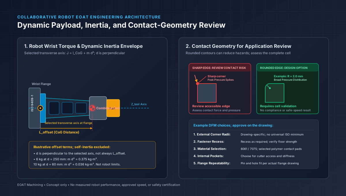
Concept schematic: axial overhang can increase transverse-axis inertia. Rounded contours and recessed fasteners are design options requiring application validation; the drawing establishes no safe speed or compliance result.
5. Physical Component Example: CNC Machined Cobot Gripper Brackets
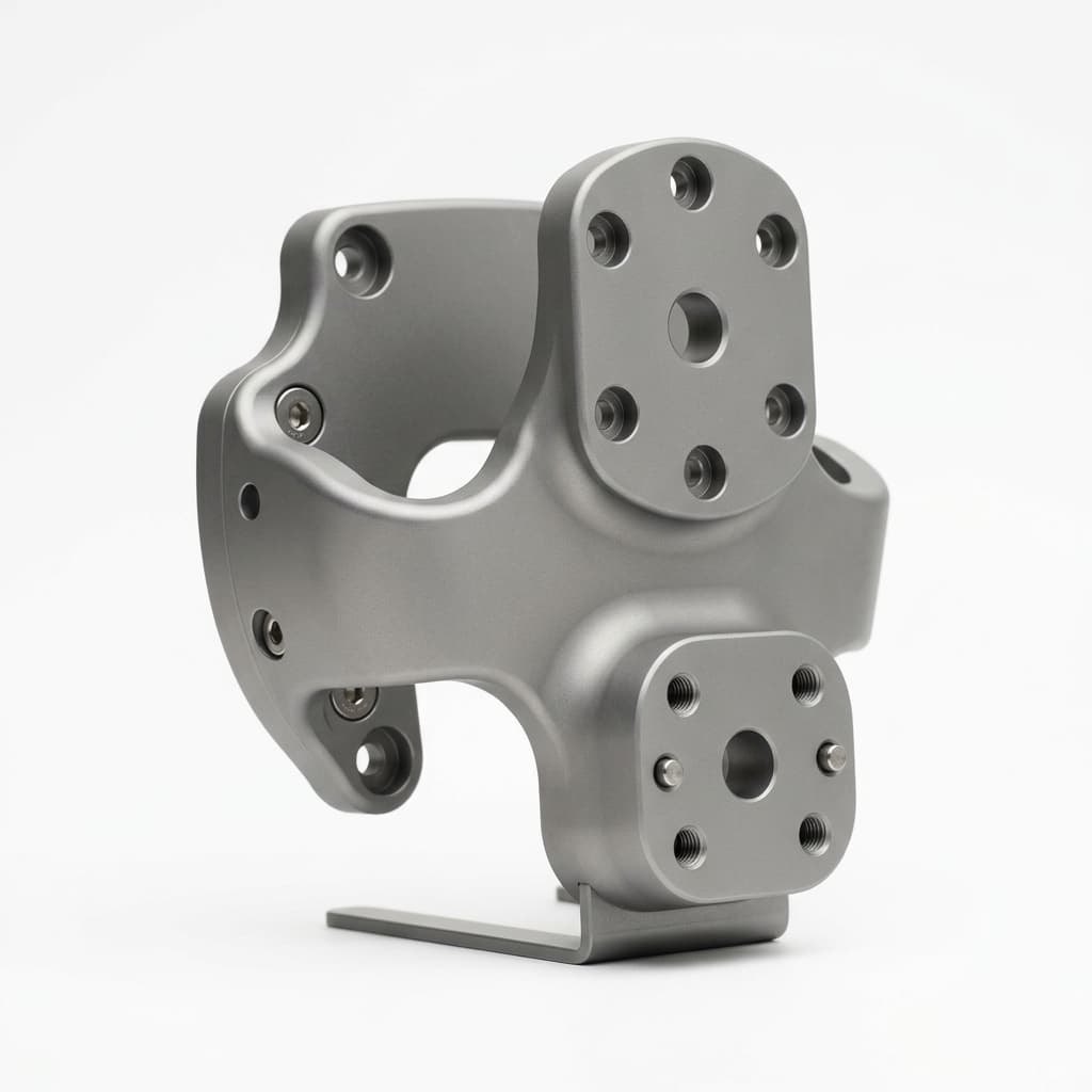
When designing custom brackets that couple collaborative actuators to part-handling fingers, monolithic CNC milling can combine locating features with pocketing in a single bracket:
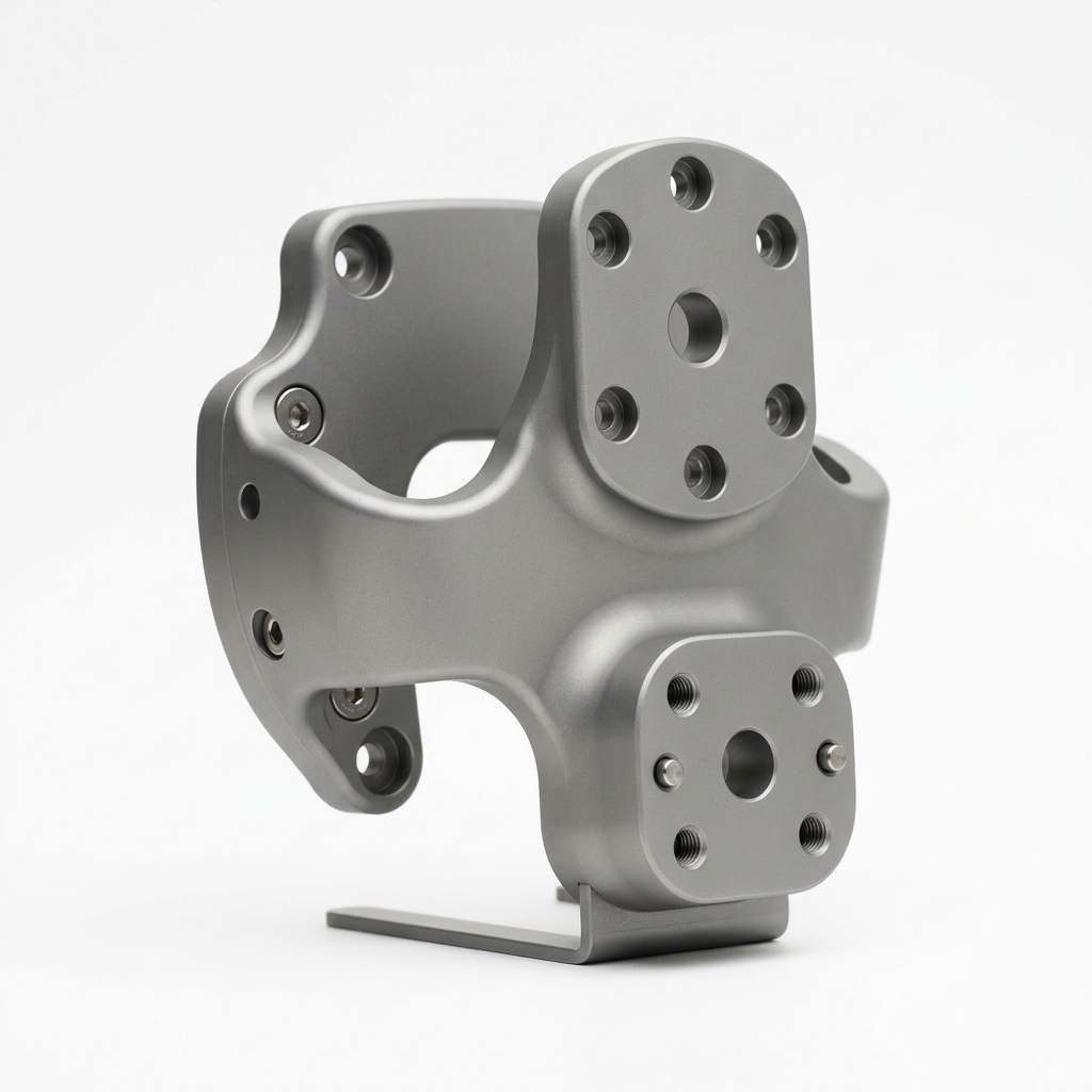
Product reference for bracket architecture only. The image does not establish alloy, weight, hole fits, edge radius, or safety performance; request a controlled drawing and inspection record for the ordered part.
For pneumatic and vacuum cobot assemblies, see our companion articles on monolithic vacuum plenum plates vs. modular tubing and custom CNC machined gripper jaws: form-fit vs. friction-grip.
6. Precision GD&T and ISO 9409-1 Flange Interfacing
The flange interface must transmit loads while locating the tool repeatably. ISO 9409-1:2004 defines circular plate interface dimensions, designation, and marking; it does not establish a coupling's load capacity. Confirm the actual robot and quick-changer drawings rather than assuming every cobot uses the same pattern.
For an interface designated ISO 9409-1-50-4-M6, the 50 mm bolt circle and four M6 positions describe only part of the interface. Verify the pilot diameter, mating male/female geometry, dowel location, thread depth, fastener engagement, and tightening instructions in the manufacturer drawing. Do not copy a pilot fit from a different robot family.
Preventing Dowel Binding and Repeatability Errors
An H7 hole designation alone does not establish a slip fit; the mating pin tolerance and finished coating condition also matter. Define the complete fit and make clear which component retains the pin. Avoid pressing a pin into a robot flange unless the manufacturer specifies that assembly method. Protect pilot edges and provide service access without weakening the joint.
Table 3: Example Drawing Controls for Supplier Review
These are proposed RFQ controls, not universal robot or ISO requirements. Approve values against the actual geometry, loads, and mating hardware before drawing release.
| Feature | Example control or drawing requirement | Inspection method | Release condition |
|---|---|---|---|
| Mounting datum face | Consider 0.020 mm flatness where justified | CMM or surface-plate measurement | Define datum area and finished condition |
| Pilot boss or recess | Manufacturer's nominal size and complete fit | Bore gauge, micrometer, or CMM | State male/female feature and mating tolerance |
| 6 mm locating hole | If specified: H7, 6.000–6.012 mm | Calibrated limit gauges | Check pin tolerance and coating allowance |
| Bolt pattern | True position to named functional datums | CMM feature verification | Define tolerance and any material-condition modifier |
| Accessible perimeter | Drawing-specific radius and burr control | Profile or radius inspection | Geometry acceptance remains separate from cell safety |
| Screw counterbore | Recess selected head while retaining floor strength | Depth and assembly check | Confirm screw engagement and service access |
7. Collaborative EOAT Procurement & RFQ Engineering Checklist
Before releasing CAD models and 2D engineering drawings to machine shops for tooling fabrication, procurement specialists and robotic cell designers should audit their quotation package against this 10-point checklist:
- 1. Cobot Flange Standard Confirmed: The mounting plate drawing explicitly cites the robot flange standard (e.g., ISO 9409-1-50-4-M6 or ISO 9409-1-40-4-M6) with mating pilot boss/recess dimensions.
- 2. Center of Gravity (CoG) & Mass Verified: 3D CAD assembly includes realistic material densities for all actuators, fasteners, and sensors; total calculated mass and CoG coordinates (Lx, Ly, Lz) are within the robot manufacturer's dynamic rating curve.
- 3. Dynamic Moment of Inertia Evaluated: Calculate relevant axes for empty, loaded, and alternative part configurations. Record the coordinate frame, inertia reference point, and units expected by the controller.
- 4. Contact Geometry Defined: Call out accessible edge treatments on the drawing and identify trapping zones, workpiece edges, and covers for the integrator. Do not label a radius as proof of ISO/TS 15066 compliance.
- 5. Fastener Recess Reviewed: Specify projection or recess limits where contact is foreseeable; check remaining floor strength, engagement length, and access to the fastener.
- 6. Pocketing DFM Optimized: Agree internal radii, cutter clearance, reach, and residual stock with the supplier. Ask for a costed alternative if a tight internal corner drives small-tool finishing.
- 7. Wall & Floor Thickness Approved: Treat the DFM ranges above as starting points. Record allowable deflection, load cases, and inspection access; obtain supplier feedback on fixturing and distortion.
- 8. Locating Dowel Fit Callout: Specify both hole and mating pin tolerances, retained-pin location, and finished condition. Review relief or venting for blind holes where needed.
- 9. Surface Finish & Anodizing Allowance: State functional surface finish and coating thickness ranges, masking, and final inspection requirements. Account for buildup in bores and threads using the selected finisher's process data.
- 10. Spare Parts Strategy Defined: The RFQ includes quotation line items for matched spare fingers, replaceable polymer wear pads, and backup adapter plates to support preventive maintenance without cell downtime.
For a quotation tied to these controls, send the completed RFQ checklist and CAD for DFM review. Include drawing revision, quantities, delivery destination, finishing, and inspection deliverables so suppliers quote the same scope.
8. Frequently Asked Questions (FAQ)
Why does my cobot trip on protective stops even though the payload is under the catalog limit?
Check the stop code, payload settings, mounting, cable loads, actual contact, and motion profile with the integrator or manufacturer. A large perpendicular CoG offset can increase inertia and acceleration demand, but that is one possible cause. Shortening the tool or revising motion may help after diagnosis; never bypass a stop or relax safety limits to compensate for an unresolved cause.
Can 3D printed polymer brackets replace CNC machined aluminum on collaborative robots?
They can suit prototypes and selected production components when the material, print orientation, temperature, load duration, and fastening method are qualified. Evaluate creep, deflection, fatigue, and insert retention rather than treating every printed bracket alike. Machined aluminum is a candidate when locating fits or stiffness govern; the choice still needs a load-specific drawing and validation plan.
How do I accurately determine the Center of Gravity and Inertia matrix for PolyScope or robot controllers?
Use CAD mass properties with assigned densities and modeled purchased components, then compare the assembly mass with the built tool. Document whether inertia is reported about the flange or combined CoG, which axes it uses, and its units. Controllers can expect a different reference point from the drawing export. In UR software that supports it, set_target_payload() updates mass, CoG, and inertia together; check the exact software manual before implementation. UR's transition-time guidance also explains that the update timing can affect motion after a payload change.
Does hardcoat anodizing affect contact radii and locating fits?
Coating thickness and dimensional buildup depend on the process and specification. Define the finished edge condition, deburring, and roughness rather than assuming anodizing preserves a safety result. Bores, pilots, and threads may need masking or machining allowances, followed by finished-part inspection. Ask the finisher for process-specific allowances; do not treat total coating thickness as identical to outward dimensional growth.
What is the recommended method to mount pneumatic valves without exceeding cobot inertia limits?
Compare a wrist-mounted manifold with an approved mounting location closer to the relevant axis. A forearm installation changes cable and hose motion, swept volume, and carried loads elsewhere in the arm; it needs manufacturer approval and application review. Longer tubing can affect pneumatic response. Choose based on the complete robot and process requirements, not inertia alone.
9. Sources and References
Source pages checked November 4, 2026. The ISO links identify the publications and their scope; they do not provide complete normative text. The tables and DFM ranges above are explanatory examples, not manufacturer limit tables, certified test results, or quotations from standards.
- ISO/TS 15066:2016 — Collaborative robots — Scope of collaborative industrial robot system and work-environment safety guidance, supplementing ISO 10218.
- ISO 9409-1:2004 — Mechanical interfaces, Part 1: Plates — Circular plate interface definition; expressly does not correlate interfaces with load-carrying ranges.
- Universal Robots — How to design for higher payloads — UR10e application-guide overview covering payload curves and tool-orientation constraints; not a rating source for other robot families.
- Universal Robots — set_target_payload(): Transition Time — Controller payload transitions and their timing. This citation supports the update discussion, not a general authorization to change safety settings.
Request a Custom Cobot Tooling Machining Quote
EOAT Machining specializes in precision CNC milling, wire-EDM, and lightweighting optimization for custom collaborative robot tooling plates, ISO 9409-1 adapter flanges, sensor mounting brackets, and gripper finger assemblies.
Our team can review your 3D STEP models for machining access, pocketing, edge treatments, and drawing completeness. Request a mass-reduction alternative where useful, while retaining robot motion approval and application safety validation with the responsible integrator.
Submit your CAD models and RFQ requirements with your cobot model code, payload specifications, target center-of-gravity offsets, and required batch quantities. You will receive an engineering DFM evaluation and manufacturing quotation tailored to your automation deployment schedule.
Author

More Posts
Semiconductor Wafer Handling EOAT Machining: 300mm FOUP Clearances, Cantilever Deflection, and PEEK Blade Tolerances
Specify semiconductor wafer handling EOAT machining: 300mm FOUP clearance budgets, PEEK blade deflection, inspection, and vacuum limits. Request a DFM review.

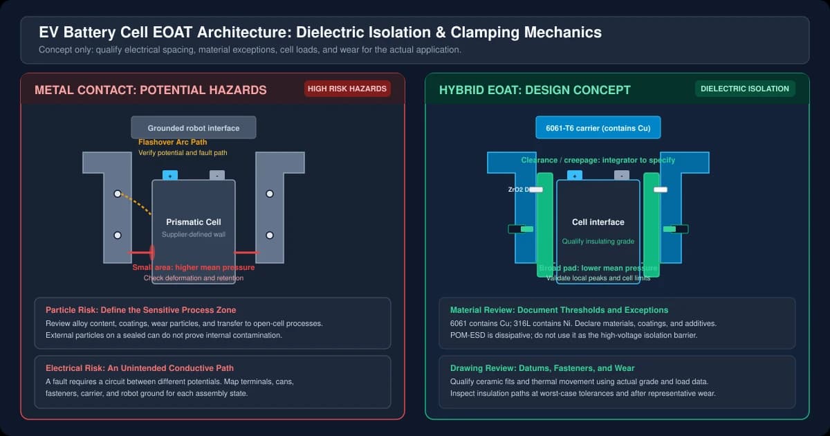
CNC Machining for EV Battery Cell EOAT: Dielectric Isolation, Cu/Zn/Ni Contamination Controls, and Thin-Wall Clamping Mechanics
Specify EV battery cell EOAT machining: dielectric vs ESD materials, Cu/Zn/Ni controls, thin-wall clamp calculations, and an RFQ checklist. Request DFM review.
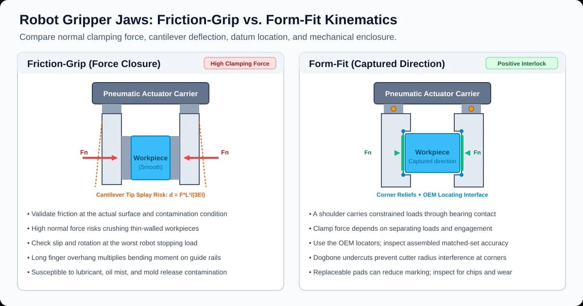
Custom CNC Machined Gripper Jaws: Form-Fit vs. Friction-Grip Engineering, Matched-Set Tolerances, and RFQ Procurement Guide
Compare custom CNC machined gripper jaws: form-fit vs friction, force sizing, matched-set tolerances, and material trade-offs. Prepare your CAD and RFQ checklist.