
Custom CNC Machined Gripper Jaws: Form-Fit vs. Friction-Grip Engineering, Matched-Set Tolerances, and RFQ Procurement Guide
Compare custom CNC machined gripper jaws: form-fit vs friction, force sizing, matched-set tolerances, and material trade-offs. Prepare your CAD and RFQ checklist.
Published and source-checked: October 28, 2026. Scope: global engineering and procurement guidance for custom CNC machined robot gripper jaws; dimensions use SI units. The calculations, beam deflection models, and tolerance tables below serve as reproducible engineering screening baselines, not measured production results, approved drawings, or blanket catalog ratings. High-acceleration robot paths, abrasive workpieces, hygienic washdown cells, and Class-A cosmetic parts require application-specific structural and surface verification.
Custom CNC machined gripper jaws and fingers bridge the gap between commercial robotic actuators (pneumatic or electric) and the manufactured workpiece. While the base gripper provides raw pneumatic stroke or servo torque, the custom top jaws dictate part location repeatability, grip stability under dynamic robot trajectory changes, and part surface preservation. In automated assembly, machine tending, and packaging, selecting between friction-grip (force closure) and form-fit (form closure / positive locking) is a fundamental architecture choice that impacts actuator sizing, cycle latency, tooling wear life, and scrap rates.
Decision summary: Choose friction-grip jaws when measured friction and available clamp force provide adequate retention without damaging the part. Consider form-fit jaws when a shoulder or pocket can carry loads in the required directions, especially for crush-sensitive parts. A contoured face alone does not establish form closure: check every escape direction and rotation. Use a metal carrier with replaceable pads when stiffness, contact protection, and maintenance requirements favor a hybrid design. Acceleration and placement accuracy alone do not establish universal selection thresholds.
For tooling programs currently preparing engineering drawings or prototype batches, request a custom gripper jaw DFM and quote review with your 3D CAD models, target actuator model, robot acceleration curves, and workpiece surface requirements.
For drawing preparation, see the EOAT tolerance and surface-finish guide and robot gripper material selection guide.
1. Where Friction-Grip Needs Additional Verification in Dynamic Cells
Check retention during the complete robot path, including these load cases:
- Maximum axis acceleration leaving a pick nest
- Wrist reorientation: tangential acceleration
α × rand centripetal accelerationω × (ω × r)at the workpiece center of mass - Sudden deceleration entering an emergency stop (E-stop) state
When a tooling engineer relies purely on flat or smooth friction-grip jaws, holding security depends entirely on the friction coefficient (μ) and normal clamping force (F_N). This creates three severe production vulnerabilities:
Dynamic Loads and Lubricant Contamination
In CNC machine tending or stamping lines, coolant, drawing lubricant, or mold release can change the friction between the pad and workpiece. Do not assign a dry-contact value to a contaminated surface. As a sensitivity example, reducing an assumed friction coefficient from μ = 0.20 to 0.10 doubles the required normal force at the same load and safety factor. These are assumed inputs, not measured coefficients for your materials. Validate the actual surface condition and minimum available operating pressure.
Over-Clamping and Workpiece Deformation
Attempting to solve slippage by installing larger bore actuators introduces a new failure mode: part crushing. Thin-walled die-cast aluminum enclosures, stamped battery casings, brass fittings, and plastic housings suffer plastic deformation or out-of-round ovality when subjected to high point clamping forces. Even if the part survives without visual crushing, residual compressive stress can cause dimensional drift after release from the gripper.
Cantilever Deflection and Contact Angle Shift
Long custom gripper fingers act as cantilever beams. When the actuator applies hundreds of Newtons at the finger tips, the beams splay outward. As the jaw faces tilt out of parallel, flat face contact degenerates into a sharp line or point contact at the inner edge. This localizes stress, mars the workpiece, and can reduce the usable contact area and holding margin.
2. Kinematic Mechanics & Force Sizing: Force Closure vs. Form Closure
To prevent undersized actuators or oversized, sluggish tooling, engineers must apply distinct mechanical models depending on whether holding is achieved through friction or geometric enclosure.
       FRICTION-GRIP (Force Closure)                FORM-FIT (Form Closure / Pocket)

          F_clamp             F_clamp                  F_clamp             F_clamp
           ====>               <====                    ====>               <====
         +-------+           +-------+                +---+               +---+
         |  Jaw  |  Work-    |  Jaw  |                |   |   Workpiece   |   |
         | (Flat)|   piece   | (Flat)|                | J |  +---------+  | J |
         |       | [=======] |       |                | a |==| Retained|==| a |
         |       |           |       |                | w |  +---------+  | w |
         +-------+           +-------+                +---+---+       +---+---+
             |                   |                        | (Pocket Lip)  |
      Relies on μ * F_clamp                   Shoulder carries constrained load
      High clamp force required               Check engagement and opening loads
Force Closure (Friction-Grip) Calculations
For equal-load-sharing fingers resisting translation along a potential slip direction, a conservative scalar screening equation is:
F_grip ≥ m × (g + a) × S / (n × μ) [N per finger]Where:
m= workpiece mass in kg.g= gravitational acceleration, approximately9.81 m/s².a= robot acceleration magnitude in m/s², excluding gravity. The sumg + abounds the case where gravity and inertial loading act in the same slip direction. For a known path, resolve the loads into the actual contact directions; do not add gravity twice to data that already includes it.S= application-specific safety factor, agreed with the gripper supplier and cell designer. The worked example below uses2.5as an assumption, not a universal requirement.n= equally loaded gripping fingers;n = 2for this example. Unequal contacts and moments require a separate analysis.μ= validated friction coefficient at the actual workpiece and pad condition.
SMC's MHZ model-selection illustration, printed page 420, derives a per-finger force of 10–20 × mg for assumed μ = 0.2–0.1 and a margin of four. This is a selection baseline; severe motion needs further allowance. Catalog conventions vary: SCHUNK's PGN-plus-P series notes define gripping force as the sum across jaws. Convert the calculated force to the chosen catalog convention before selecting a model.
Form Closure (Form-Fit) Calculations
A shoulder can carry the load component directed into it through bearing contact. It does not retain the workpiece in an open direction or automatically prevent rotation or jaw opening. For the same aligned scalar load case:
F_load = m × (g + a)                   [N]
σ_bearing = F_load / A_bearing         [N/mm² = MPa]
Design bearing stress = S × σ_bearing
Compare the design stress with the allowable bearing stress of both contacting materials. Check shoulder bending, shear, fatigue, edge distance, contact sharing, and overturning moments separately. The actuator still needs adequate force to maintain engagement against separating loads. There is no universal percentage reduction in clamp force, and a pocket does not establish retention after loss of air or electrical power.
Numerical Worked Example: High-Acceleration Part Handling
This is a hypothetical, reproducible comparison of load paths, not a hardware test or actuator recommendation. Inputs:
- Workpiece mass:
m = 2.5 kg. - Robot acceleration:
a = 3g = 29.4 m/s², using roundedg = 9.8 m/s²for this example. - Aligned gravity-plus-inertia load:
m × (g + a) = 2.5 × 39.2 = 98 N. - Assumed
μ = 0.20,S = 2.5, and two equally loaded fingers.
Scenario A: Pure Friction-Grip Jaws
F_grip = 2.5 × 39.2 × 2.5 / (2 × 0.20) = 612.5 N per finger
Total normal force across two fingers = 1,225 N
At μ = 0.10, the requirement rises to 1,225 N per finger. Confirm force at the actual finger length and minimum supply pressure, then check part deformation. Bore diameter alone cannot determine gripping force because gripper mechanisms differ.
Scenario B: Form-Fit CNC Machined Pocket Jaws
Assume a shoulder carries the entire 98 N load over an effective bearing area of 4 × 25 = 100 mm²:
Nominal bearing stress = 98 / 100 = 0.98 MPa
Design bearing stress with S = 2.5: 2.45 MPa
This calculation screens bearing stress only. It does not establish a suitable actuator size or mass saving. Specify pocket engagement, tolerances, separating forces, workpiece strength, jaw moments, and pressure-loss behavior before releasing the design.
3. Engineering Comparison Matrix: Friction vs. Form-Fit vs. Hybrid Jaws
| Technical Parameter | Flat / Knurled Friction Jaws | Form-Fit Conforming Pocket Jaws | Hybrid Metal Carrier with Polymer Inserts | Procurement & Engineering Verification |
|---|---|---|---|---|
| Primary Holding Mechanism | Force closure: normal clamping force × friction coefficient (μ) | Form closure: geometric mechanical interlock into CNC pocket | Metal backbone with polymer contact; friction or form-fit retention | Verify whether part tolerance variations permit rigid form closure. |
| Required Clamping Force | Determined by friction, load direction, and margin; see per-finger calculation | Determined by engagement and separating loads; no universal weight multiplier | Determined by load path, pad friction, and compression | Compare force at actual finger length and minimum pressure. |
| Dynamic Inertia / E-Stop | Verify slip and rotation at worst motion load | Verify every escape direction, shoulder strength, and opening force | Check retention plus pad compression and insert attachment | Document stopping loads and loss-of-power behavior. |
| Part Surface Marring Risk | Sliding or serrations may mark the surface | Broad contact may reduce pressure, but debris and edges can still mark | Pads can reduce marking; trapped chips can still scratch | Test the specified finish and cleanliness condition. |
| Incoming Part Variation | Stroke may accommodate size changes; contact geometry still matters | Rigid pockets can jam or lose engagement at tolerance extremes | Compliance depends on pad geometry, grade, and compression | Check tolerance extremes and incoming-part capability. |
| Machining Complexity & Cost | Simple faces and mounting features may reduce setup work | Profile milling, reliefs, or EDM can add cost | Insert pockets and fasteners add parts and assembly | Request comparable quotes with the same inspection scope. |
| Service Life & Maintenance | Inspect wear and holding margin | Inspect engagement surfaces and datum wear | Establish pad replacement from measured wear and retention | Specify service access and acceptance limits, not assumed cycle life. |
Need to resolve an actuator interface or tolerance stack? Send the jaw drawing and load cases for an RFQ review before freezing the pocket geometry.
4. Structural Integrity: Preventing Cantilever Deflection & Tip Spread
A frequent root cause of intermittent gripper failure is ignoring the cantilever beam mechanics of the finger design. When gripping a part at an extended distance from the actuator slide carriage, the finger deflects under load.
Cantilever Deflection Model
Treating the gripper finger as a beam rigidly fixed at the actuator mounting face and loaded at the gripping contact point distance (L):
δ = F_clamp × L³ / (3 × E × I_xx)
Where:
δ= Linear deflection at the finger tip [mm]F_clamp= Clamping force applied at the tip [N]L= Finger overhang length from the actuator mounting face [mm]E= Modulus of elasticity of the jaw material (use the selected grade and condition datasheet; convert GPa toN/mm²by multiplying by 1,000 when lengths use mm)I_xx= Area moment of inertia about the bending axis:I_xx = b × h³ / 12for a rectangular cross-section of widthband bending thicknessh.
The angular deflection (tip splay angle θ) is:
θ ≈ F_clamp × L² / (2 × E × I_xx) [radians]
                   FINGER DEFLECTION & TIP SPLAY

       Actuator Carriage           Finger Overhang (L)
      +-----------------+======================================+
      |                 |                                      | <--- Unloaded
      |                 |--------------------------------------+
      |                 |  \
      |                 |    \ Deflected under clamp load
      +-----------------+      \===============================+
                                  \ Angular tilt (θ)           |
                                    \                          | <--- Tip splay
                                      \========================+
                                            F_clamp (Downward tip load)
Consequences of Tip Splay
The acceptable tip displacement and angle come from the part-location and contact-pressure budgets; there is no universal displacement threshold. As the loaded finger bends, its contact face rotates. Instead of distributing clamping pressure over the intended 20 mm × 40 mm contact pad, contact collapses onto a narrow line at the upper corner. This concentrates the force, punches through surface anodizing or paint, and induces unpredictable part pivoting.
Actuator Guide Moment Overload
Use the selected model's finger-length, finger-mass, force, and moment limits. SCHUNK's PGN-plus-P data identifies its tabulated moments as static values; do not relabel them as dynamic ratings. A simple transverse tip-load moment is:
M = F_clamp × L
Map the moment to the catalog axes and include the workpiece and finger inertia. Use consistent units: N × mm gives N·mm; divide by 1,000 for N·m. The beam model assumes a uniform section, a rigid mounting face, small elastic deflection, and a tip load; it does not model guide compliance or fatigue.
Exceeding the catalog moment rating accelerates guide play, degrades repeatability, and causes premature actuator seal failure.
DFM Rules to Maximize Finger Rigidity Without Adding Mass:
- Tapered Beam Geometry: Rather than using a constant rectangular bar, machine a linear taper along the finger height (
h). For an ideal tip load, bending moment decreases toward the tip. Optimize the taper with stress and deflection checks; a linear taper does not automatically produce uniform bending stress. - Integrated Stiffening Ribs: Pocket out the non-contact backside of the finger, leaving continuous perimeter ribs and diagonal truss webs. Compare section stiffness about the actual bending axis; pockets can reduce stiffness in other directions and introduce stress concentrations.
- Material Upgrading: When space envelopes constrain finger thickness (
h), a higher-strength aluminum grade can increase yield margin, subject to its supplied condition and product form. However, because common structural aluminum grades have similar elastic modulus (roughly70 GPa), deflection is not reduced by alloy strength alone; consider a larger section, shorter overhang, or steel when the stiffness budget cannot otherwise be met; include the added mass in the robot load calculation.
5. Visualizing the Kinematics: Friction Clamp vs. Form-Fit Conforming Pocket
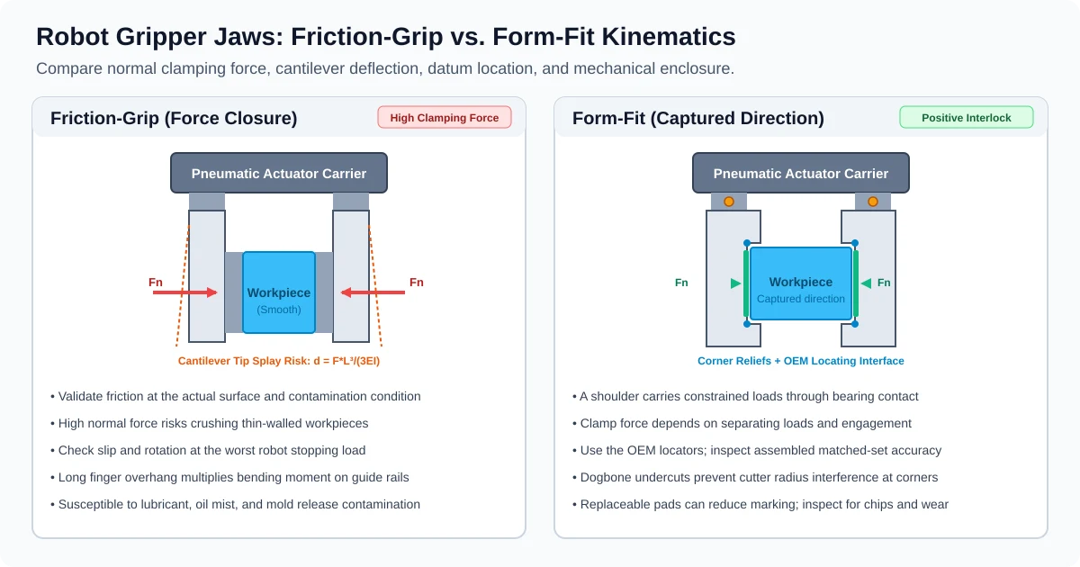
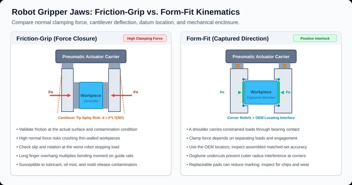
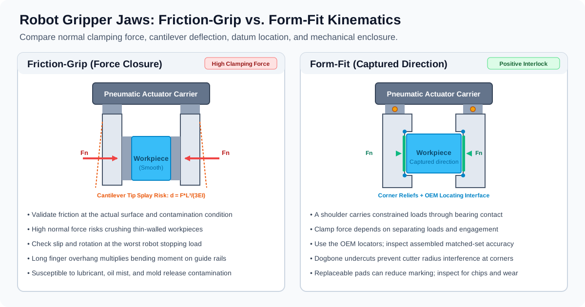
Kinematic architecture comparison: Friction-grip (left) requires high normal force to overcome inertial slip, creating cantilever bending risks. Form-fit (right) utilizes precision CNC machined pockets and dowel datums to carry loads in constrained directions through bearing contact. Conceptual diagram, not to scale; it does not establish actuator sizing or measured performance.
Open the scalable vector architecture diagram to inspect the locating features and force paths.
In physical production environments, achieving repeatable part location requires tight control over the mounting interface between the actuator carriage and the custom jaws.
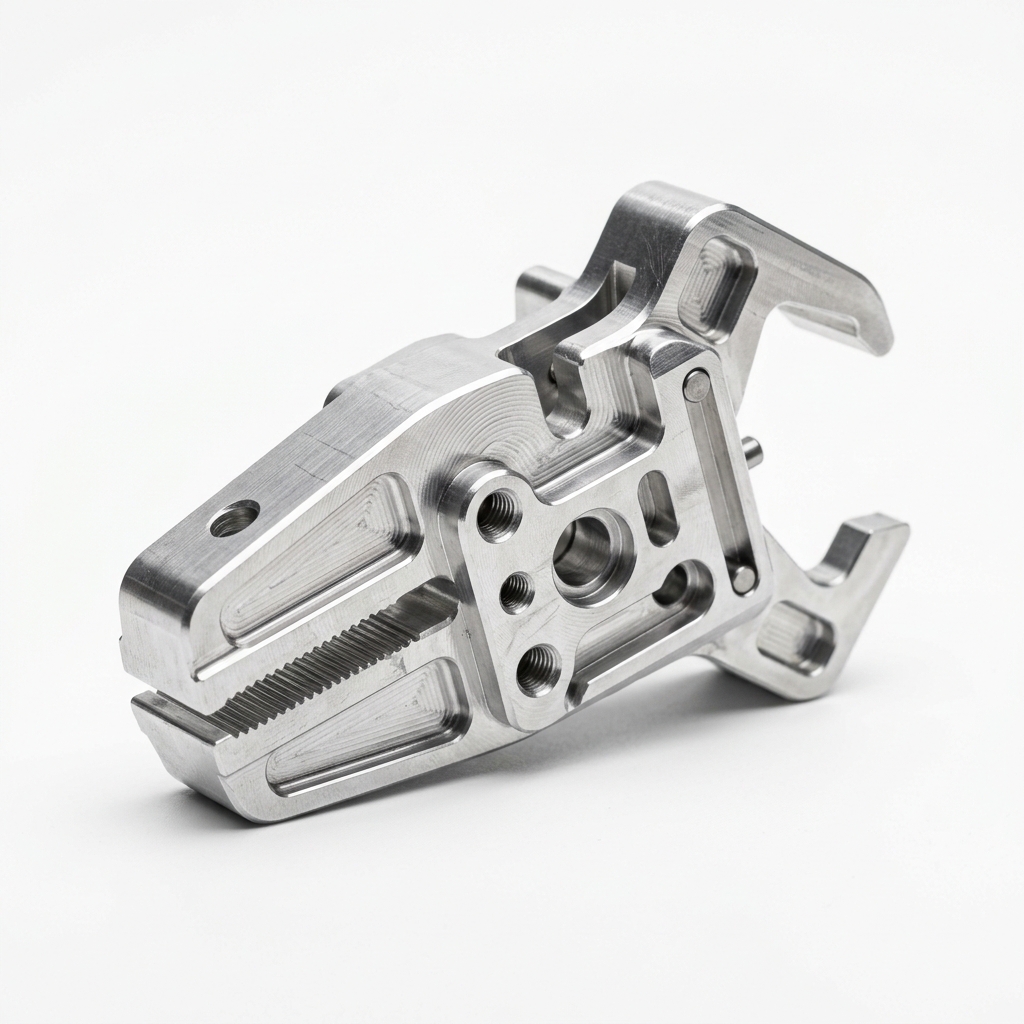
Illustrative jaw geometry showing mounting holes, pockets, and shaped contact features. An image cannot verify bore fit, alloy, matched-set accuracy, or production inspection results.
6. DFM Rules for CNC Machining Custom Gripper Jaws
Designing high-performance gripper fingers requires translating kinematic requirements into practical CNC machining features that machinists can reliably produce and inspect.
Matched-Set Machining Protocol
Set-to-set variation can shift the part centerline even when each jaw meets its individual size tolerances. For accuracy-critical nests, define matched-set acceptance in the RFQ:
- Agree the manufacturing method for controlling paired datums and contours; a shared fixture is one option, not proof of accuracy.
- Inspect the pair on the intended mounting interface or a correlated fixture, including assembled centerline and height mismatch.
- Mark a set ID and left/right identity (for example,
SET-042-LandSET-042-R). Supply the inspection record with the pair.
Individual spare jaws are acceptable only when interchangeability is explicitly toleranced and verified. The example fixture below illustrates a shared setup; it does not replace functional inspection.
       MATCHED-SET GANG MILLING FIXTURE

       +-----------------------------------------------+
       | CNC Vise Base / Dedicated Fixture Plate       |
       |                                               |
       |   +---------------+       +---------------+   |
       |   |  Jaw Blank A  |       |  Jaw Blank B  |   |
       |   |  (Left)       |       |  (Right)      |   |
       |   |    [Contour]  |  <->  |  [Contour]    |   |
       |   |    (H7 Bore)  |       |  (H7 Bore)    |   |
       |   +---------------+       +---------------+   |
       |            Single Milling Setup               |
       |       Identical Tooling & Zero Offsets        |
       +-----------------------------------------------+
Actuator Mounting Interface: Reamed Dowel Bores vs. Clearance Holes
Use the actuator manufacturer's locating features: these may be dowels, centering sleeves, keys, or fitted shoulders. Screw clearance holes alone do not provide a repeatable locating datum; joint slip also depends on preload and applied loads.
- Locator compatibility: Match the OEM interface. Do not add holes to the actuator body or base jaws without manufacturer approval.
- Bore size: If the drawing specifies a 4 mm H7 hole, its limits are 4.000–4.012 mm, not a symmetric ± tolerance; see the MISUMI fit table. H7 defines the hole limits only; specify the mating pin fit and positional control separately.
- Avoid over-constraint: Where the interface permits, one round locator plus a relieved diamond pin or a correctly oriented slot can accommodate center-distance variation. A diamond pin and a slotted hole are different solutions.
- Fasteners: Follow the actuator drawing for screw size, strength class, torque, and maximum engagement depth. Determine jaw thread engagement from material and load; generic thread-length rules must not override the OEM limits.
Internal Corner Relief: Dogbones and Undercuts
When milling a pocket to nest a rectangular or square workpiece, rotating CNC end mills cannot produce sharp 90° inside corners. If an end mill with radius R cuts the pocket, the workpiece's sharp external corner will hit the internal fillet radius, preventing the part from seating flush against the reference datums.
To resolve this without expensive secondary wire-EDM operations:
- Specify dogbone corner reliefs or corner undercuts on the 2D drawing.
- Size the relief radius to allow standard end mills (
R1.5 mmorR2.0 mm) to plunge past the intersection, leaving clearance for the sharp corner of the workpiece. - Tolerance on relief cuts can be generous (
+0.2 mm / -0.0 mm), as they are non-contact features.
Draft Angles and Air Bleed in Deep Pockets
In high-speed assembly, pulling a tight-tolerance part out of a deep form-fit nest can create a partial vacuum that causes the part to stick inside the jaw when opening. Furthermore, surface tension from residual oil can lock the part in place.
- Draft Angles: Consider an application-specific release draft on non-locating walls;
1–2°is an initial design example to validate against engagement depth and part variation. - Vacuum Bleed / Air Passages: Consider vent holes or milled bleed channels behind the seat, sized for release time, cleaning access, and residual section strength; validate release under the actual coolant condition.
Chip Shedding & Coolant Drainage
For CNC machine tending grippers operating inside the machining envelope:
- Slope or chamfer exposed non-locating surfaces where practical; keep chips away from reference surfaces without reducing their supporting area.
- Machine continuous drainage slots through the bottom of pocket nests where they do not compromise retention or stiffness; verify drainage and carryover during trials.
7. Material Selection & Modular Replaceable Wear Inserts
Selecting the right material for custom gripper jaws balances payload weight, fatigue resistance, machinability, and part preservation.
| Material Grade | Structural / Contact Role | Grade Information to Request | Typical Selection Reason | Limitations to Verify |
|---|---|---|---|---|
| 6061-T6 Aluminum | Lightweight carrier | Temper, product form, finish | Machinability and low moving mass | Wear, thread strength, and contact pressure. |
| 7075-T6 Aluminum | Higher-strength carrier | Temper and environment compatibility | More yield margin where section size is constrained | Similar elastic stiffness to other aluminum alloys; strength alone does not reduce bending. |
| 17-4PH Stainless | Steel carrier or wear feature | Heat-treatment condition and certification | Strength and wear requirements | Mass, corrosion environment, and cleaning compatibility; grade alone does not establish hygienic suitability. |
| 4140 Pre-Hardened Steel | Rigid carrier or durable contact | Supplied hardness and treatment | Wear and stiffness under repeated loading | Corrosion protection and moving mass. |
| POM-C Acetal | Replaceable contact pad | Exact resin grade and conditioning | Low mass and machinable contact geometry | Creep, chemical compatibility, and lower stiffness; POM-C is distinct from Delrin POM-H. |
| Unfilled PEEK | Specialized contact insert | Exact grade, temperature/load data | Applications needing a qualified polymer at elevated temperature | Cost, creep, and process cleanliness; temperature capability is grade and load dependent. |
| Cast Polyurethane | Compliant contact pad | Formulation and Shore hardness | Compliance and potentially higher friction | Measure friction with actual oil/coolant; verify compression set, swelling, and wear. |
These are selection roles, not guaranteed material properties. Use the supplier's grade-specific datasheet and certificate for strength, hardness, temperature, and chemical limits.
Engineering Modular Replaceable Inserts
A modular hybrid architecture can separate structural stiffness from contact-pad replacement:
- Structural Base Jaw: Precision CNC machined aluminum with a specified finish. Agree coating thickness, dimensional growth allowance, and masking with the finisher; inspect functional dimensions after finishing.
- Machined Insert Pocket: A precision milled pocket on the contact face with locating shoulders to support the insert against shear forces.
- Replaceable Wear Pad: A small machined or molded contact insert: POM-C, PEEK, polyurethane, or a metal such as brass, selected for the application.
- Rear-Mounted Fasteners: Secure the wear pad via counterbored screws installed from the backside of the aluminum jaw. Keep heads below the contact surface throughout the allowed wear range; rear access must be checked in the assembled tool, and debris can still damage the workpiece.
       MODULAR HYBRID JAW ARCHITECTURE

           Structural Base Jaw (7075-T6)
       +------------------------------------+
       |                                    |
       |    [Counterbored Bolt Clearance]   |
       |                  |                 |
       |                  v                 |
       |         +-----------------+        |
       |         | Replaceable Pad |        | <--- PEEK / POM-C / Brass
       |         | (Smooth Contact)|        |      Zero screw heads on face
       |         +-----------------+        |
       |                  ^                 |
       |         Supported by Pocket Walls  |
       +------------------------------------+
8. Comprehensive GD&T and Machining Inspection Specifications
The following are illustrative RFQ discussion targets, not tolerances mandated by a general standard. The OEM mounting drawing and the part-location tolerance stack govern the final values. Use one declared GD&T system and edition on the released drawing. Define datum A as the mounting plane and choose B/C from the actual locating interface; hole size alone cannot guarantee assembled repeatability.
| Feature / Dimension | Example Target or Drawing Requirement | Basis / Limitation | Manufacturing & Inspection Method | Functional Quality Objective |
|---|---|---|---|---|
| Actuator Mounting Datum Face (A) | Flatness ≤ 0.010 mm; Ra ≤ 0.8 µm, if the interface budget requires it | Explicit design targets, not an ISO 2768 default | Finish milling or grinding; flatness and roughness measured separately | Limit tilt and mounting distortion. |
| Locating Dowel Bore Size | Example: 4 mm H7 = 4.000–4.012 mm | ISO 286 size limits; mating pin and geometry are separate | Ream or finish bore; suitable calibrated plug or bore gauges | Control locator clearance without claiming TCP accuracy. |
| Locator Pattern Position | Basic dimensions plus a diametrical position zone per the OEM datum scheme | Specify datum references and applicable modifiers; do not write “± true position” | CMM or correlated fixture | Verify installation without locator binding. |
| Contoured Nest Profile | Example: total surface-profile zone 0.030 mm relative to the defined datums | Design target; check incoming-part extremes and release clearance | Profile milling; CMM or suitable profile measurement | Control contact geometry without jamming. |
| Matched Pair Height Difference | Example: absolute difference ≤ 0.015 mm in the assembled fixture | Pair-level acceptance, separate from each jaw's size tolerance | Inspect the serialized pair on a correlated mounting fixture | Limit paired height and centerline mismatch. |
| Corner Reliefs (Dogbones) | Model tool radius, positive clearance, and minimum residual wall | Drawing-specific geometry; not a generic DFM standard | Relief milling; profile or optical check | Clear workpiece corners while preserving shoulder strength. |
| Fastener Counterbores | Size, depth, clearance, and engagement per the chosen fastener and OEM drawing | Verify maximum screw penetration and finished head recess | Depth gauge and assembly check | Avoid interference and bottomed-out screws. |
9. Procurement and RFQ Engineering Checklist
Before releasing CAD models and 2D drawings to precision CNC machine shops for quotation, procurement teams and tooling engineers should audit their technical package against this 9-point verification checklist:
- 1. Actuator Verification: Actuator make, exact model code, stroke per jaw, and manufacturer mounting pattern drawing are documented.
- 2. Kinematic & Load Definition: Workpiece mass, maximum robot Cartesian acceleration (
a_max), centripetal acceleration, and E-stop deceleration rates are specified. - 3. Holding Strategy Justified: The selection between friction-grip and form-fit is verified against the workpiece geometry, allowable clamping force, and cycle speed.
- 4. Matched-Set Requirement Explicit: 2D drawings explicitly mandate that paired jaws (or 3-jaw sets) have agreed pair-level acceptance, functional inspection, and matching set IDs; specify interchangeable spares only if validated.
- 5. Datum & Dowel Hole Tolerances: The locating scheme matches the actuator drawing, with hole and pin fits, positional controls, and final-finish acceptance defined; review trapped air or fluid in blind press-fit holes.
- 6. Corner Relief Geometry Modeled: Nesting corners that need clearance include modeled reliefs sized to the selected cutter and workpiece corner geometry; preserve the minimum structural wall.
- 7. Surface Finish & Anodize Masking: Mounting datums and contact surfaces specify required roughness; coating thickness, growth allowance, masking, and inspection after finishing are explicit.
- 8. Modular Insert Serviceability: If polymer or brass wear pads are utilized, service access and minimum pad thickness before replacement are verified in the assembled tool.
- 9. Spare Parts & Replacement Strategy: The RFQ includes unit pricing for initial tooling plus replacement matched sets (quantity based on wear trials, replenishment lead time, and downtime cost) to ensure seamless changeovers upon scheduled preventive maintenance.
10. Frequently Asked Questions (FAQ)
Can 3D printed (additive) jaws replace CNC machined jaws for production cells?
Additive jaws can suit prototypes and qualified production applications. Polymer stiffness, creep, build orientation, wear, and contact cleanliness must be assessed for the actual duty. Metal additive jaws may need finish machining of mounting datums and bores. Choose by validated loads, life, accuracy, and total cost rather than assuming a process is always suitable. See the CNC machining versus 3D printing EOAT comparison.
How should matched jaw pairs be controlled during re-orders?
Use complete serialized matched pairs when the drawing controls geometry at set level. Specify revision, material and finish condition, pair inspection, and the assembly datum fixture on the reorder. An individual replacement is reasonable when the design defines and verifies interchangeability; recheck assembled part location after replacement.
What prevents parts from sticking inside deep form-fit nests during release?
Sticking is typically caused by two factors: geometric friction lock and air pressure vacuum sealing. To reduce sticking, validate these measures against release time and part variation:
- Consider release draft on non-locating sidewalls without reducing required engagement.
- Incorporate micro-radius blend transitions on all pocket entry corners.
- Drill a cross-vented vacuum bleed passage behind the nest and verify pressure equalization during opening.
- If passive release is insufficient, evaluate a controlled ejector or air assist; verify part trajectory, surface damage, and contamination constraints.
How do you balance custom finger length against actuator guide life?
Check the chosen model's force-versus-finger-length curves, permissible finger projection, mass limits, and moment ratings in its actual catalog. Include the workpiece center of mass and jaw inertia, with static and dynamic contributions distinguished. Reducing acceleration changes dynamic loads but cannot repair an excessive static moment or an out-of-range finger geometry. Shorten the reach, relocate the actuator, or select a suitable guide arrangement when required.
When should a hybrid jaw (metal base + polymer pad) be specified instead of solid polymer?
Use a metal carrier when a solid polymer finger cannot meet the calculated deflection, creep, or attachment requirements within the available envelope. A thin replaceable pad can protect the contact surface while the carrier supplies stiffness. Verify pad retention, friction, wear thickness, and cleanliness; a polymer pad does not guarantee scratch-free handling. Short, lightly loaded polymer fingers can still be appropriate after validation.
11. Sources and References
Sources checked October 28, 2026. Manufacturer instructions apply to the stated models; the worked loads and RFQ tolerance targets in this article are illustrative engineering analysis, not manufacturer test results or universal requirements.
- SMC — MHZ Parallel Style Air Gripper catalog, Model Selection, printed page 420 — Per-finger friction-sizing convention, the assumptions behind its weight multiplier, and the need for further allowance under severe motion.
- SCHUNK — PGN-plus-P 80-1-V technical data and series notes — Total gripping-force convention, finger-length dependence, and static load limits for this specific gripper; not a recommendation for the worked example.
- SCHUNK — PGN-plus-P Assembly and Operating Manual, document 389753, version 28.00 — Finger sizing and assembly requirements (§2.4 and §5.2). Distinguish custom top fingers from internal base jaws; modifications to the actuator require manufacturer approval.
- MISUMI meviy — Fit tolerance tables and drawing guidance (Japanese) — H7 hole deviations for the over-3-to-6-mm size band and the distinction between hole and shaft tolerances. Consult the specified ISO 286 edition and mating-component drawing for released dimensions.
Prepare a Machinable Gripper Jaw RFQ
EOAT Machining provides precision CNC milling, wire-EDM, and matched-set inspection for custom robot gripper jaws, fingers, and part-nesting fixtures. Whether your automation cell requires lightweight 7075-T6 aluminum fingers with dogbone pocket reliefs or hybrid assemblies with replaceable PEEK contact inserts, our engineering team audits your CAD models for tool access, deflection resistance, and datum repeatability before cutting metal.
Submit your CAD models and RFQ requirements with your target actuator model, workpiece drawing, material specifications, and required spare set quantities. You will receive an engineering DFM review and quotation tailored to your production schedule.
Author

More Posts
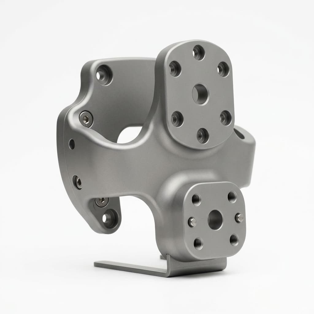
Cobot EOAT Machining: Inertia & RFQ Guide
Plan cobot EOAT machining with payload and inertia calculations, contact-edge risk checks, flange tolerances, and an RFQ checklist. Request a CAD/DFM review.
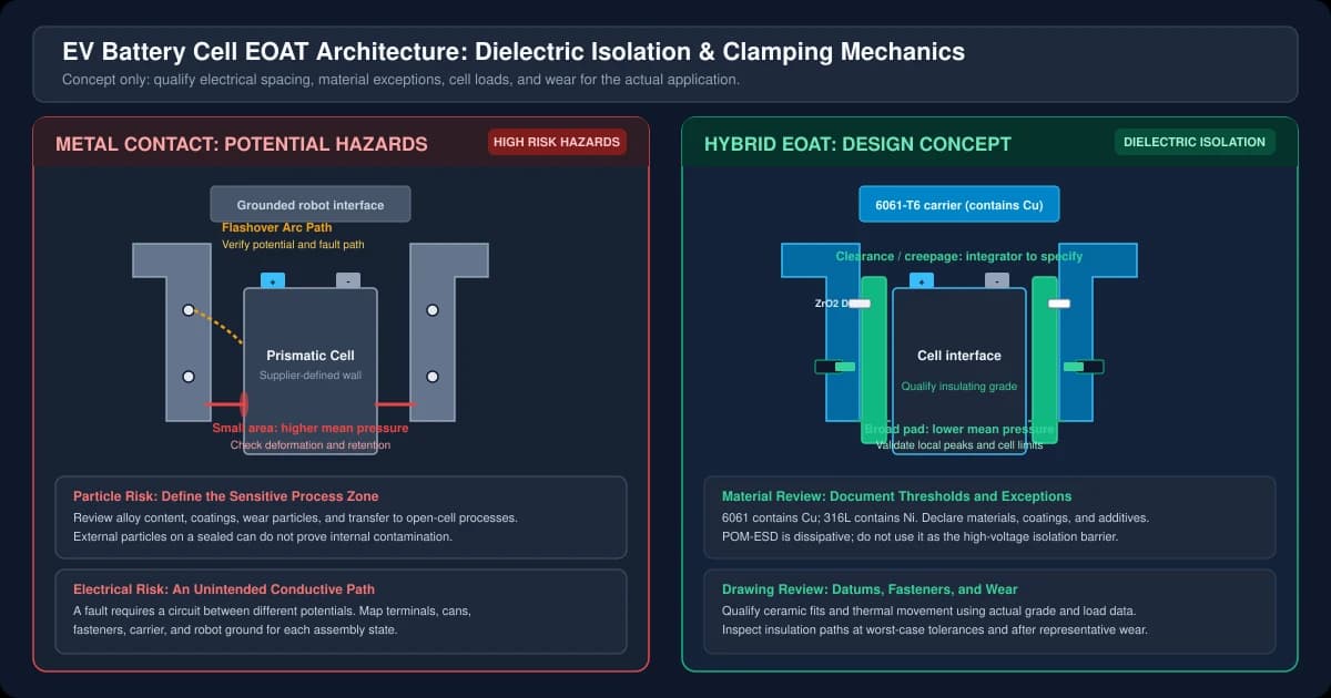
CNC Machining for EV Battery Cell EOAT: Dielectric Isolation, Cu/Zn/Ni Contamination Controls, and Thin-Wall Clamping Mechanics
Specify EV battery cell EOAT machining: dielectric vs ESD materials, Cu/Zn/Ni controls, thin-wall clamp calculations, and an RFQ checklist. Request DFM review.
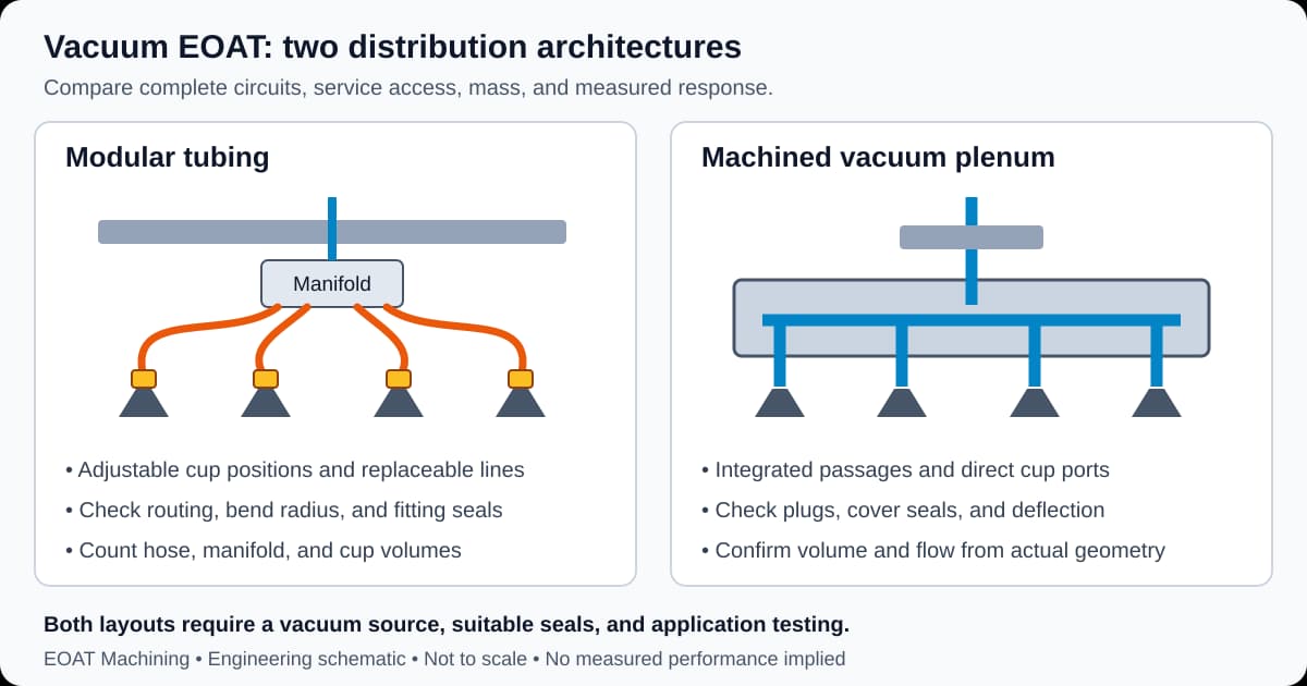
Monolithic Vacuum Plenum Plates vs. Modular Tubing in EOAT: CNC Machining, Sealing Tolerances, and Procurement Guide
Compare monolithic vacuum plenum plates vs modular tubing EOAT. Check evacuation, seal tolerances and RFQ acceptance criteria, then request a CAD review.