
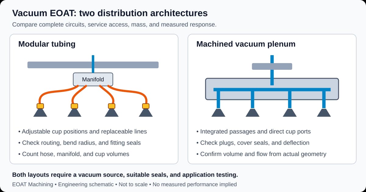
Monolithic Vacuum Plenum Plates vs. Modular Tubing in EOAT: CNC Machining, Sealing Tolerances, and Procurement Guide
Compare monolithic vacuum plenum plates vs modular tubing EOAT. Check evacuation, seal tolerances and RFQ acceptance criteria, then request a CAD review.
Published and technically reviewed: October 26, 2026. Scope: global engineering and procurement guidance for industrial vacuum EOAT; dimensions use SI units. The calculations below are reproducible screening examples, not measured production results or approved drawings. Porous workpieces, hygienic processes, and precision wafer handling require application-specific validation.
Monolithic vacuum plenum plates vs. modular tubing EOAT is a choice about layout stability, pneumatic response, maintenance access, and manufacturing cost. A machined plate can shorten distribution paths and consolidate interfaces. A modular assembly can be easier to reconfigure and repair. Neither architecture has a universal picks-per-minute or robot-acceleration crossover.
Decision summary: Choose modular tubing when cup positions change frequently, standard replacement parts matter, or measured response already meets the cycle budget. Consider a CNC machined plenum when a stable cup layout, restricted wrist envelope, or measured distribution losses justify custom machining. Compare complete tool mass, attainable vacuum, leak rate, and release time before approving either option.
For a tooling project already at drawing stage, request a CAD and sealing review with the cup layout, vacuum source curve, robot motion profile, and required acceptance tests.
1. The High-Speed Pick-and-Place Dilemma: Inspect the Distribution Circuit
Delayed grip confirmation and intermittent vacuum loss can originate at the workpiece, cups, generator, valves, filters, or distribution circuit. Record vacuum at the generator and the most remote cup during an actual pick before assigning the cause to tubing.
Mechanical Fatigue, Routing, and Cleanability
- Fittings and hose movement: Side loads, inadequate insertion, abrasion, or repeated bending close to a fitting can create leaks. Check the selected tube and fitting ratings, insertion depth, strain relief, and service interval.
- Wrist rotation and kinking: Route hoses through the full robot motion envelope and respect the manufacturer's minimum bend radius. A restricted line can delay evacuation or isolate a cup; the outcome depends on check valves, leakage, and retained volume.
- Cleaning access: Exposed hose bundles can obstruct cleaning, while enclosed channels can retain contamination. Material compatibility and drainability must be evaluated for both architectures; a metal plate alone does not establish washdown or clean-in-place suitability.
The SMC vacuum equipment selection guide discusses circuit volume, piping pressure loss, workpiece leakage, and response time (printed pages 009 and 015). These are diagnostic inputs, not evidence that every modular assembly will fail.
2. Architectural Comparison: Modular Tubing vs. Monolithic CNC Plenums
- Modular extrusion and tubing assembly: Structural framing, brackets, commercial cups, and replaceable tubing connect the vacuum source to the workpiece. Local ejectors can also be used on a modular tool.
- Machined distribution plate: Cross-drilled passages in a single billet, with sealed access plugs, combine mounting and vacuum distribution. A pocketed base with a bolted, sealed cover is a two-piece plenum, rather than a strictly monolithic part. Both need accessible, inspectable seals.
Engineering and Procurement Comparison Matrix
| Technical Parameter | Modular Extrusion and Tubing | Machined Vacuum Plenum | Procurement Check |
|---|---|---|---|
| Internal volume | Depends on tube ID, length, fittings, and cups | Depends on channel geometry, pockets, ports, and cups | Calculate both complete circuits; a large pocket can exceed tubing volume. |
| Leak interfaces | Tube connections and component seals | Access plugs, cup ports, and cover seals where used | List each interface and test the finished assembly; neither is inherently leak-free. |
| Profile and mass | Adjustable, with routing clearance required | Can integrate mounting and reduce stack height | Compare CAD mass, center of gravity, and wrist inertia against robot limits. |
| Rigidity | Depends on frame joints and bracket geometry | Depends on plate section, ribs, supports, and mounting | Check deflection under pressure and robot loads rather than assuming zero flexure. |
| Washdown access | Replaceable lines, with possible external crevices | Fewer external lines, with possible inaccessible internal passages | Specify chemistry, temperature, drainage, seals, and cleaning access. |
| Sensors and zones | Easy to add tees, valves, or separate branches | Can integrate taps and isolated zones | Confirm service access, cross-zone leakage, and the open-cup fault response. |
| Cost and lead time | Often favors prototypes and changing layouts | Adds CAD, machining, finishing, and inspection effort | Compare installed quotes and spare-part strategy; do not assume a downtime payback. |
For purchasing, calculate payback as incremental installed cost divided by verified net savings per period. Include engineering changes, replacement seals, inspection, and spare tools; if savings have not been measured, report payback as unknown.
3. Fluid Dynamics and Cycle Time: A Reproducible Volume Example
Less volume can improve evacuation response, but channel restrictions, leakage, generator performance, and valve timing can dominate. The following calculation isolates volume so that its assumptions can be checked.
Simplified Evacuation Model
For a sealed, rigid, approximately isothermal volume with constant effective pumping speed at the evacuated volume and negligible ultimate pressure:
t = (V / S_eff) × ln(P_start / P_target)
Vis the complete evacuated volume, in liters.S_effis effective volumetric pumping speed at the evacuated volume, in liters per second; it is not the catalogue's free-air or ANR flow rating.P_startandP_targetmust both be absolute pressures in the same units.- A target of 35 kPa absolute corresponds to −66.3 kPa gauge only when local atmospheric pressure is 101.3 kPa.
This model follows the mass balance dP/dt = −S_eff × P / V under those assumptions. With a pressure-dependent source, use its performance curve or measured pressure trace. Workpiece leaks, cup deformation, valve delay, and non-negligible ultimate pressure are excluded from this calculation.
Eight-Cup Worked Example — Assumed Geometry and Flow
- Eight hoses, each 5.5 mm ID and 600 mm long, contain
8 × π × (5.5 / 2)² × 600 / 1000 = 114.0 cm³of air. This excludes all cups, fittings, and manifold cavities. - Assume those additional cavities contribute 46.0 cm³, giving 160 cm³ total. Assume a proposed plate circuit contains 40 cm³ total, including its cups and ports. These totals require confirmation from CAD or volume measurement.
- At the same assumed
S_eff = 1.0 L/s, starting at 101.3 kPa absolute and ending at 35 kPa absolute, predicted times are 170 ms and 43 ms, respectively: a 75% reduction in this modeled evacuation component.
The approximately 127 ms saving is not automatically a line-cycle saving. At 40 picks per minute, a cycle lasts 1.5 seconds. If the entire modeled saving lies on the critical path and nothing else limits throughput, the theoretical rate becomes about 43.7 picks per minute. If evacuation overlaps robot travel or the upstream process sets the rate, output may remain unchanged.
Validate by logging the same cup pressure threshold, supply pressure, workpiece, valve logic, release condition, and motion profile for both tools. Include failed picks and pressure recovery after a deliberately open cup.
4. Visualizing the Architectures: Tubing Bundle vs. Channeled Plenum
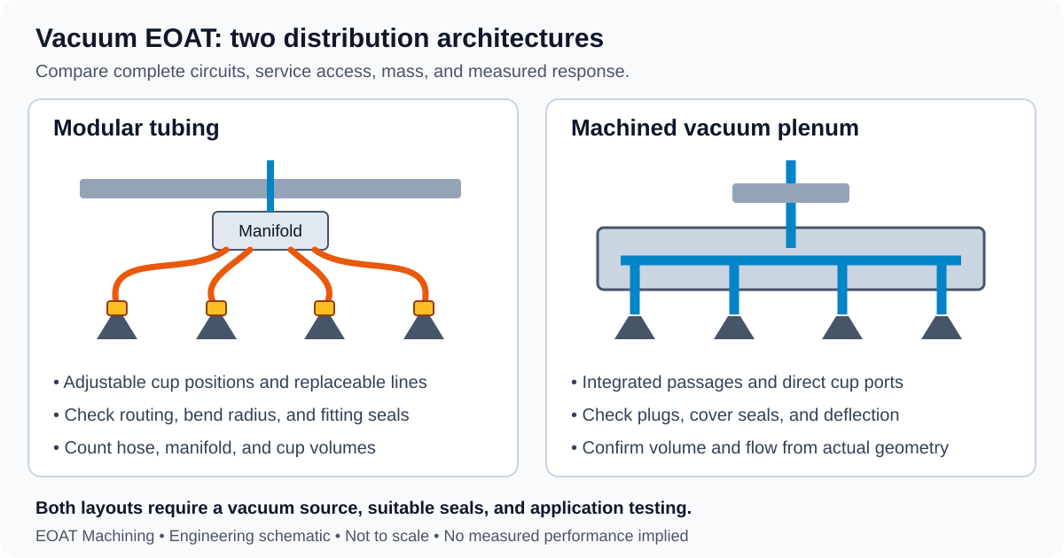
Architecture schematic, not a product photograph or a measured performance comparison. A machined plate still needs a vacuum supply connection, port seals, and sealed drilling entries or a cover joint.
Open the scalable architecture diagram to inspect the labels.
5. DFM Rules for CNC Machining Vacuum Plenums and Gasket Glands
Internal Channels: Cross-Drilling vs. a Two-Piece Plate
- Cross-drilled runners: Straight drilled intersections preserve a single main body. Specify burr removal, chip extraction, access-plug retention, and leak testing. Parallel G threads need an appropriate face or bonded seal; tapered NPT connections need their specified sealing method. The thread forms are not interchangeable.
- Two-piece milled plenum: A pocketed base and removable cover allow more complex paths and cleaning access. Seal layout, cover stiffness, bolt preload, and fastener spacing must be designed together. A universal 40–60 mm bolt pitch cannot establish sealing performance.
Rectangular vs. Retained Glands
Rectangular glands suit many captive static cover seals. An exposed workpiece gasket may need retention during separation or blow-off. Select a dovetail profile from the seal supplier's dimensions and cutter access requirements; a generic undercut angle is insufficient. Check the assembly for both vacuum and the maximum intended positive-pressure release pulse.
Squeeze and Fill: Calculate the Tolerance Stack
The Parker O-Ring Handbook, sections 3.6–3.7 explains squeeze and gland fill. It describes a general fill range of 60–85%, with 75% as an optimum; the correct design also depends on seal compound and service conditions. Do not apply solid O-ring guidance directly to foam gaskets.
For a hypothetical rectangular static gland, assume a 3.00 ± 0.08 mm round seal, groove depth 2.40 ± 0.05 mm, and width 4.00 ± 0.05 mm:
- Nominal squeeze:
(3.00 − 2.40) / 3.00 = 20.0%. - Worst-case squeeze:
(2.92 − 2.45) / 2.92 = 16.1%minimum;(3.08 − 2.35) / 3.08 = 23.7%maximum. - Nominal sectional fill:
π × 3.00² / (4 × 4.00 × 2.40) = 73.6%; the dimensional extremes give approximately 67.5–80.3%.
This example excludes groove corner radii, seal stretch, swelling, temperature, coating growth, and face deflection. Verify those effects and the selected seal's recommendations before releasing the drawing. A groove tolerance alone does not guarantee a squeeze percentage.
6. Vacuum Gasket Groove and CNC Machining Specifications
These are RFQ starting points and drawing inputs, not universal machining standards or guaranteed supplier capability. Final acceptance belongs on the approved drawing after seal selection and tolerance analysis.
| Engineering Parameter | Example or Required Input | Manufacturing and Inspection | Functional Check |
|---|---|---|---|
| Gland depth | Example: 2.40 ± 0.05 mm for the seal above | Finish-machine and measure relative to the sealing face | Recalculate minimum and maximum squeeze using actual seal tolerance. |
| Gland width | Example: 4.00 ± 0.05 mm for the same gland | Profile-mill and inspect the full path | Check fill after swelling, stretch, and coating effects. |
| Gland corner radii | Specify the selected seal's minimum bend radius | Confirm cutter radius and inspect corners | Avoid local stretching, pinching, and unsupported gasket joints. |
| Sealing surface | Discuss Ra 0.8 µm as an initial finish target; supplier approval required | Specify finish, lay, scratches, and post-coating condition | Roughness alone does not establish leak-tightness. |
| Plate flatness | Example: 0.05 mm over a 300 mm face, subject to the compression budget | Identify the measurement support condition and inspect after finishing | Include operating deflection and mating-part flatness. |
| Vacuum ports | Specify G parallel or NPT tapered thread, size, and sealing detail | Inspect threads, spotfaces where required, and internal deburring | Test the assembled fitting and preserve service access. |
Include the stainless vacuum manifold sourcing guide in a material review when washdown exposure and payload compete with layout requirements.
7. Structural Integrity: Preventing Plate Deflection Under Vacuum
Pressure loading applies to each wall's actual exposed projected area, rather than automatically to the tool's external envelope. For a fully exposed 400 × 600 mm chamber face at an 80 kPa differential:
F = ΔP × A = 80,000 Pa × 0.400 m × 0.600 m = 19,200 N = 19.2 kN
This is a distributed chamber-wall load, not the available lifting force at the cups. Cup holding force must be assessed separately using effective cup area, actual pressure, leakage, friction, acceleration, moments, and the application's safety factor.
DFM Review for Deflection Control
- Wall thickness and unsupported span: Select thickness from material stiffness, unsupported geometry, boundary conditions, and combined pressure and robot loading. A fixed 4 mm floor or 6–8 mm cover is not a generally valid design rule.
- Ribs, pillars, and fasteners: Check load transfer and joint compression without creating flow restrictions, uncleanable pockets, or leaks between zones. Pillars only support the cover if the contact and load path are designed for that purpose.
- Analysis and testing: Set allowable deflection from the remaining gasket compression and part-position budget. Evaluate vacuum, blow-off, mounting preload, and robot loads; then inspect and leak-test the representative assembly. A universal 0.03 mm limit cannot certify a design.
8. Material Selection: Aluminum, Stainless Steel, and Polymers
| Material | Potential Reason to Choose It | Limitation to Resolve Before Purchase |
|---|---|---|
| 6061-T6 aluminum | Machinability and relatively low tool mass | Check cleaning chemistry, coating growth, seal-face condition, and channel coverage. |
| 7075-T6 aluminum | Higher strength where stress limits the design | Higher strength does not imply a comparable stiffness increase; assess corrosion and finishing. |
| 304 stainless steel | Corrosion resistance in compatible environments | Account for mass, thread galling, crevices, and chloride exposure. |
| 316L stainless steel | Candidate for more demanding corrosion conditions | It is not immune to chloride attack; verify actual chemistry, temperature, and cleanability. |
| POM-C acetal | Low mass and non-marring contact features | Check creep, thermal movement, chemical compatibility, and seal preload retention. |
Specify the exact stock grade and condition with material certification. For anodizing, agree thickness, sealing treatment, masking, and post-finish gland dimensions with the supplier. Do not assume a nominal 50 µm coating reaches every internal passage or makes aluminum compatible with caustic cleaning. Sanitary or food-contact suitability requires a complete process and material assessment.
9. Procurement and RFQ Engineering Checklist
Before requesting comparable quotes, confirm that the package includes:
- Geometry and scope: STEP solid model and controlled 2D drawing, cup layout, each vacuum zone, plugs, cover, and supplied components.
- Operating conditions: Workpiece porosity and surface, required pick and release times, vacuum source curve, supply pressure, temperature, and cleaning chemistry.
- Seal stack: Seal part number, compound, cross-section tolerance, groove dimensions, corner radii, squeeze/fill extremes, surface finish, and flatness budget.
- Robot interface: Robot OEM flange drawing, payload, center of gravity, inertia limits, and fastener engagement. Use ISO 9409-1:2004 for the applicable plate-interface dimensions; the standard does not rate the completed EOAT's load capacity.
- Port and zone map: Thread standard, sealing method, valve and sensor access, and isolation requirements when one cup or zone is open.
- Finishing and cleanliness: Coating/passivation requirements, masked features, internal burr and chip removal, and inspection after finishing.
- Leak-test method: Defined test volume, fixture, blanking arrangement, starting absolute pressure, stabilization time, sensor resolution, temperature, duration, and allowed pressure rise. Specify cross-zone testing separately.
- Dynamic acceptance: Representative workpiece trials for grip confirmation, release, full robot motion, and fault response; agree the sample count and acceptance thresholds before ordering.
- Commercial scope: Quantity, revision control, first-article records, delivery milestones, replacement seals, spare-tool strategy, and responsibility for assembly and testing.
Illustrative leak-test acceptance, requiring buyer approval: A blanked 40 cm³ circuit starts near −80 kPa gauge at the recorded local atmosphere, stabilizes, and is isolated for 60 seconds. An agreed pressure rise of no more than 1.5 kPa corresponds to about 0.59 mL/min of equivalent air at 101.3 kPa, assuming constant temperature and volume: Q_ref = V × ΔP / (P_ref × Δt). Subtract fixture leakage and account for instrument uncertainty. This example is not a universal pass limit, and it does not represent leakage through the real workpiece.
10. Frequently Asked Questions
When is modular tubing preferred over a machined plenum?
Use modular tubing when cup positions or product mix change frequently, field replacement is important, or measured performance meets the cycle requirement. A well-routed modular tool can also serve continuous production. Production volume alone does not justify replacement; compare measured losses and total installed cost.
How do you verify internal channel airtightness?
Blank the specified outlets, stabilize temperature and pressure, isolate the source, and record pressure rise over an agreed interval. Document test volume, fixture leakage, and sensor uncertainty. Test zone isolation separately. A pressure-rise result checks the assembly under those conditions; it does not establish grip performance on a porous part.
Can a machined plenum handle independent vacuum zones?
Yes, if passages, seals, ports, and valves keep the zones isolated. Test the intended fault case with a neighboring zone open. A common upstream source or a leaking cover seal can couple otherwise separate zones, so a zone count on the drawing is insufficient.
How should washdown corrosion be addressed?
Specify cleaning chemistry, concentration, temperature, exposure duration, drainage, and all wetted materials, including seals and plugs. Compare aluminum finishes and stainless grades for those conditions. Neither hard anodizing nor a 316L designation by itself establishes compatibility or hygienic acceptance.
What fastener spacing should a split plenum use?
Calculate spacing and preload from cover stiffness, seal compression force, pressure reversal during blow-off, thread engagement, and the permitted deflection. Confirm with inspection and testing. A 40–60 mm pitch may be a layout assumption, but it is not an acceptance rule for every plate.
11. Sources and References
Sources reviewed October 26, 2026. Supplier documents support the stated principles; numerical tooling scenarios and suggested RFQ inputs above are explicitly identified as examples.
- Parker O-Ring Handbook, ORD 5700 — sections 3.6–3.7, printed page 3-9, explain squeeze and gland fill; section 3.11 discusses vacuum applications. Use the selected seal's application guidance for final dimensions.
- SMC — Model Selection: Vacuum Equipment — printed page 009 covers leakage and response-time selection, page 014 defines flow and pressure terms, and page 015 covers excessive circuit volume and piping pressure loss. It does not substantiate a fixed percentage improvement from a machined plate.
- ISO 9409-1:2004 — Manipulating industrial robots: Mechanical interfaces, Part 1: Plates — defines principal dimensions, designation, and marking for plate interfaces. Confirm the robot OEM drawing and load limits separately.
Prepare a Machinable Vacuum EOAT RFQ
EOAT Machining can review custom plate and manifold requirements against the supplied geometry, sealing plan, and inspection scope. Confirm achievable tolerances, finishing effects, lead time, and acceptance evidence in the quotation rather than treating the example values in this guide as a capability guarantee.
Send your CAD and RFQ requirements with the workpiece, cup/zone map, operating pressures, robot limits, material/finish requirements, quantity, and proposed leak and cycle tests. This gives engineering and purchasing a common basis for comparing a modular assembly with a machined plenum.
Author

More Posts
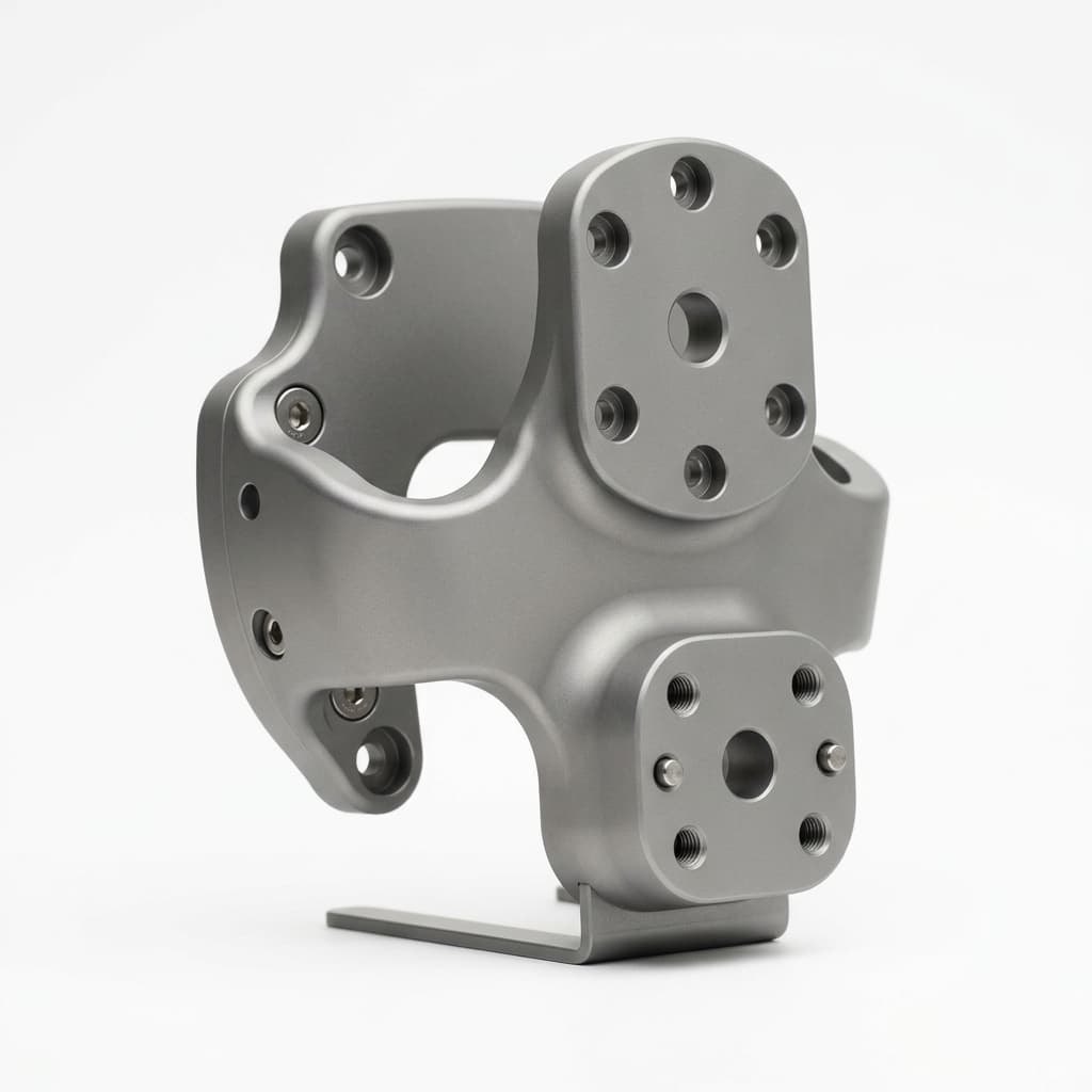
Cobot EOAT Machining: Inertia & RFQ Guide
Plan cobot EOAT machining with payload and inertia calculations, contact-edge risk checks, flange tolerances, and an RFQ checklist. Request a CAD/DFM review.
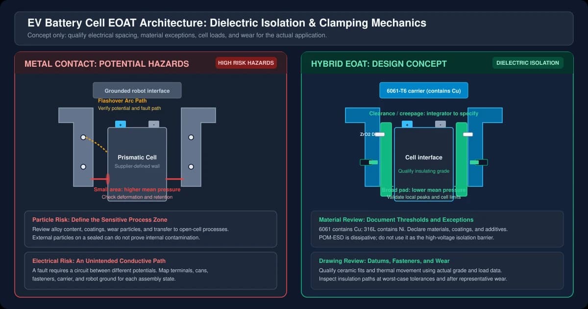
CNC Machining for EV Battery Cell EOAT: Dielectric Isolation, Cu/Zn/Ni Contamination Controls, and Thin-Wall Clamping Mechanics
Specify EV battery cell EOAT machining: dielectric vs ESD materials, Cu/Zn/Ni controls, thin-wall clamp calculations, and an RFQ checklist. Request DFM review.
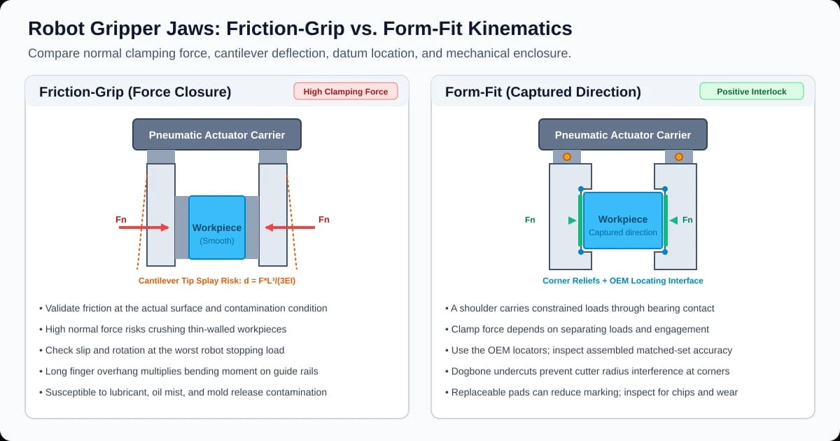
Custom CNC Machined Gripper Jaws: Form-Fit vs. Friction-Grip Engineering, Matched-Set Tolerances, and RFQ Procurement Guide
Compare custom CNC machined gripper jaws: form-fit vs friction, force sizing, matched-set tolerances, and material trade-offs. Prepare your CAD and RFQ checklist.