
CNC Machining for EV Battery Cell EOAT: Dielectric Isolation, Cu/Zn/Ni Contamination Controls, and Thin-Wall Clamping Mechanics
Specify EV battery cell EOAT machining: dielectric vs ESD materials, Cu/Zn/Ni controls, thin-wall clamp calculations, and an RFQ checklist. Request DFM review.
Published and editorially reviewed: November 1, 2026. Scope: global engineering and procurement guidance for custom EV battery cell end-of-arm tooling (EOAT); dimensions use SI units. The calculations and tolerance tables are illustrative screening examples, not measured production results, approved drawings, or safety certification. Electrical isolation requires the integrator's application-specific assessment; cell contact limits and cleanliness acceptance criteria require the cell manufacturer's approval. Pouch-cell vacuum handling needs a separate contact and leakage assessment.
Automated assembly of electric vehicle (EV) battery packs—spanning prismatic, blade, and large cylindrical cells (such as 4680 formats)—combines electrical isolation, particle control, and delicate casing requirements. A single isolated cell's terminal voltage differs from the hundreds of volts possible across a connected series string. The voltage between each contacted surface and the robot ground depends on the actual assembly state and cell construction; pack voltage must not be assigned automatically to every cell can.
Three separate risks guide the design: a conductive tool completing an unintended electrical path, tool-generated particles reaching sensitive cell processes, and clamping loads damaging the casing or internal layers. A dielectric hybrid tooling architecture can combine a CNC machined aluminum carrier with insulating polymer contact pads and ceramic datums, provided the assembled tool is qualified for its intended electrical and mechanical conditions.
Decision summary: Use an electrically qualified unfilled insulating polymer, such as an appropriate PEEK grade, between potentially live surfaces and the metal carrier. Carbon-filled POM-ESD is dissipative and must not serve as the high-voltage isolation barrier. Specify Cu/Zn/Ni restrictions and permitted exceptions in the RFQ rather than calling an alloy “metal-free.” Use broad contact pads or approved support ledges, then verify contact force, local deformation, and emergency-stop retention against cell-specific limits.
For automated battery module or pack tooling programs currently in development, request a custom battery EOAT engineering and DFM review with your cell solid models, cell electrical potential map, dry-room dew point conditions, and target robot cycle profile.
For broader gripper jaw mechanics and cleanroom baseline standards, consult our custom gripper jaws form-fit vs. friction guide and cleanroom and ESD-safe EOAT machining guide.
1. The High-Voltage Handling Challenge: Dielectric Breakdown and Flashover Mechanics
During module stacking, cell insertion, and busbar joining, a gripper may encounter isolated cells, partially connected modules, or connected strings. Record the maximum potential difference between every accessible terminal, can, fastener, carrier, and robot ground in each process and fault state. State of charge alone does not establish a safe handling voltage.
The can may be connected to a terminal, isolated, or floating, depending on the cell design. Metallic contact creates a short-circuit risk when it completes a circuit between different potentials; contact with one isolated surface does not by itself prove a fault loop exists. Obtain the cell supplier's electrical interface drawing and include exposed fasteners and worn contact pads in the fault assessment.
CONVENTIONAL FLASHOVER PATH (UNSHIELDED)
Robot Wrist (Ground) <--- Steel Jaw <--- Exposed Fastener <=== [Possible Fault Path] ===> Live Surface

ENGINEERED DIELECTRIC BARRIER (HYBRID)
Robot Wrist (Ground) <--- Al Carrier <--- Ceramic Dowel <--- [Qualified Insulating Pad] ---> Cell Can
Creepage and Clearance Coordination (IEC 60664-1)
Use IEC 60664-1 as an insulation-coordination reference where applicable to the equipment, alongside the governing machine and electrical requirements. Its official lifecycle record identifies the 2020 edition consolidated with Amendment 1:2025. Two distinct dimensions must appear on the drawing:
- Clearance distance (air path): The shortest distance through air between conductive parts. Determine it from the required impulse withstand, insulation function, altitude, field conditions, and applicable equipment requirements. Working DC voltage alone does not select a clearance.
- Creepage distance (surface path): The shortest distance along an insulating surface between conductive parts. Determine it from working voltage, pollution degree, and the actual grade's comparative tracking index (CTI). Do not assign Material Group I to all PEEK or POM grades, or infer pollution degree solely from a low dry-room dew point.
Drawing release inputs (no universal spacing value):
Maximum working voltage and required impulse withstand: integrator to specify
Insulation function, pollution degree, altitude, and polymer-grade CTI: verify
Required clearance and creepage: select from the governing standard
Minimum as-built paths: include fasteners, slots, contamination, and wear
Verification: approved drawing review and assembled-tool electrical test plan
Counterbore Recess Depths for Metallic Fasteners
A frequent mistake in custom gripper design is bolting an insulating polymer pad onto an aluminum jaw frame using standard socket head cap screws inserted from the front or side. If the screw head is left flush with the polymer face, the metallic screw acts as an electrical bridge, reducing the effective clearance distance to zero.
Prefer rear mounting into blind holes when the load path and polymer thread strength permit it. If front-facing fasteners are unavoidable:
- Dimension recess depth, remaining solid insulation, and air and surface paths from the approved electrical requirements; a fixed recess depth cannot establish compliance.
- Specify an insulating cap's material, retention, inspection, and replacement criteria. A removable plug does not automatically restore a continuous insulation barrier.
- Verify pad compression, screw penetration, and wear allowance at worst-case tolerances so the cell-facing surface cannot expose metal in service.
2. Technical Cleanliness and Contamination: The Cu/Zn/Ni Exclusion Protocol
Distinguish open-cell processing from sealed-cell transfer. Particles have a more direct route to electrodes and electrolyte before sealing; sealed-cell handling still needs controls for external contamination and downstream transfer. VDA 19.1 and ISO 16232 provide technical-cleanliness inspection frameworks. The customer must define acceptance limits, sampling area, extraction method, and relevant particle materials; these references do not establish a universal Cu/Zn/Ni alloy-content ban.
Why Cu/Zn/Ni Controls Need a Defined Exposure Zone
Unwanted metallic particles can create conductive bridges or participate in electrochemical reactions inside a cell. The outcome depends on particle size, chemistry, location, cell design, and operating conditions. Do not treat external dust on an intact sealed can as proof of internal contamination or a guaranteed thermal event.
For procurement, identify which tool surfaces contact the cell, which components can shed into an open-cell zone, and which remain outside that zone. Request an alloy and coating declaration for each relevant part, then agree on particle extraction and analysis with the customer.
CONTAMINATION CONTROL PATH:
Tooling Wear ---> Particle Release ---> Possible Transfer to Sensitive Cell Process
              ---> Control by Material Declaration, Wear Inspection, and Particle Testing
The Festo F1A Battery Specification
Festo's battery-production product overview, version 2.0 dated February 1, 2023, describes F1A as a manufacturer classification excluding metals with more than 1% copper, zinc, or nickel as alloy constituents, subject to listed exceptions. Those exceptions include nickel in steels and chemically nickel-plated surfaces, as well as certain electrical components. It is not a universal automotive standard or a declaration that every constituent contains zero Cu/Zn/Ni.
- 316L contains nickel. Its acceptance must follow the specified exception and the customer's particle requirements; passivation does not remove bulk nickel.
- 6061-T6 contains copper as an alloy constituent. Check the material certificate against the agreed threshold. Do not substitute copper-rich 7075 under the same low-copper assumption.
- Brass, zinc plating, and nickel finishes require an explicit disposition. A customer's stricter exclusion can override a supplier classification. Record approved exceptions by component and finish rather than declaring all such surfaces universally banned.
3. Thin-Wall Clamping Mechanics: Pressure Distribution on Aluminum Cans
Prismatic and blade-format cells can have thin aluminum casings with broad faces that are sensitive to local bending. Obtain the actual wall construction, allowed contact zones, and force-displacement limits from the cell supplier. A nominal wall thickness, alloy designation, or format name cannot establish the allowable gripper load.
Localized Pressure vs. Cell Deformation Limits
Narrow fingers and uneven pad contact concentrate loads. Check three separate acceptance criteria:
- Can deformation: Permanent dents or deflection can interfere with module stack dimensions and cooling interfaces.
- Internal loading: The cell supplier must assess whether the contact pattern creates unacceptable compression of internal layers.
- Retention: A pad that protects the can must still retain the cell during acceleration, braking, and the defined emergency-stop condition.
Use mean pressure for preliminary comparison, then check local peaks and deformation with an appropriate model or representative cell test:
P_mean = F_normal_per_jaw / A_effective_per_jaw

Where:
P_allowable = cell-supplier-approved value for the actual contact zone
Mean pressure does not predict edge loading, can buckling, or internal damage.
CAN WALL DEFLECTION AND CLAMPING GEOMETRY
Narrow Metal Fingers (Point Loading): Broad Dielectric Pad with Bottom Lip:
F_clamp F_clamp F_clamp F_clamp
===> <=== ===> <===
+--------+ +--------+ +--------+ +--------+
| Narrow | | Narrow | | Broad | | Broad |
| Metal | Can Wall | Metal | | PEEK | Can Wall | PEEK |
| Finger | Buckles | Finger | | Pad | Flat & | Pad |
| | ->( )<- | | | (Large | Uniform | (Large |
| | | | | Area) | [======] | Area) |
+--------+ +--------+ +--------+ +--------+
+--------+ +--------+
| Bottom | | Bottom |
| Ledge | | Ledge |
Smaller area raises mean pressure Larger area lowers mean pressure
Check local deformation Verify ledge load and retention separatelyForce Sizing Screening Example
The following is a hypothetical calculation, not a measured cell or friction test. Inputs must be replaced with application data:
- Cell mass:
m = 2.5 kg - Vertical robot acceleration leaving the nest:
a_z = 15.0 m/s^2 - Gravitational constant:
g = 9.81 m/s^2 - Total dynamic load:
F_dynamic = m * (g + a_z) = 2.5 * (9.81 + 15.0) = 62.025 N - Assumed friction coefficient:
mu = 0.22; measure the actual pad/cell pair, including wear and contamination. - Illustrative load factor:
S = 2.5; select the required factor through the application risk assessment.
If holding purely by frictional clamping across n = 2 opposing jaws:
F_clamp_friction = F_dynamic * S / (n * mu)
                 = (62.025 * 2.5) / (2 * 0.22)
                 = 155.0625 / 0.44
                 = 352.4 N per jaw (rounded)
If the designer uses a narrow gripper finger with a contact area of only 20 mm * 30 mm = 600 mm^2 (0.0006 m^2):
- Resulting mean pressure:
P_mean = 352.4 N / 0.0006 m^2 = 0.587 MPa. - With the same force over an
80 mm * 100 mm = 8,000 mm^2pad, mean pressure becomes0.044 MPa. Neither result establishes a safe cell load without the supplier's acceptance limits. - Sensitivity: halving the assumed friction coefficient to
mu = 0.11doubles required normal force to approximately705 N per jaw. Confirm whether the gripper's catalog force is quoted per finger or for the pair.
The Form-Fit Bottom Support Solution
An approved bottom support ledge (form-fit shoulder) can transfer vertical load through bearing and bending rather than relying entirely on side friction. Check the ledge, its root, cell-bottom contact zone, and fasteners for the factored load of 155.1 N in this example; include unequal load sharing and lateral moments.
If a separate lateral-load analysis selected 80 N per jaw, an 8,000 mm^2 side pad would have a mean pressure of 0.010 MPa. That force is an independent assumption, not a calculated retention requirement or a guaranteed percentage reduction. Verify access to the cell bottom, support engagement, and release clearance before selecting this architecture.
4. Dry-Room Environmental Dynamics: Polymer Stability at -40°C to -60°C Dew Point
Moisture-sensitive cell processes can require very dry conditions. Treat -40°C to -60°C dew point as an example RFQ envelope, not a universal requirement for sealed-cell assembly. Specify ambient temperature separately: dew point is not the polymer's operating temperature. Obtain the actual humidity, temperature, conditioning time, and cleaning exposure from the production-line owner.
Moisture Desorption and Polymer Embrittlement
Water absorption values depend on grade, test method, temperature, and conditioning. Do not convert a datasheet's water-uptake percentage directly into dimensional shrinkage:
- PA6 / PA66: Moisture conditioning can change dimensions and mechanical response. Require dry-state data and conditioned-part inspection before accepting a precision datum application.
- POM-C: A candidate for economical insulating contact pads when the specific grade's electrical, thermal, and dimensional data meet the requirement.
- Unfilled PEEK: A candidate for more demanding insulating interfaces. Obtain CTI, dielectric, wear, and conditioning data for the supplied grade; it is not a zero-particle material.
Dry-room qualification sequence:
Record stock grade and conditioning history -> Machine and inspect baseline
-> Condition at the agreed environment -> Remeasure critical datums
-> Cycle representative loads -> Inspect wear, particles, and electrical paths
5. Visualizing the Architecture: Unshielded Metal vs. Engineered Dielectric Hybrid Tooling
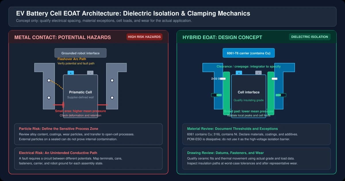
Concept diagram, not a certified design or test result: compare potential metal-contact and particle hazards with insulating pads, a metal carrier, ceramic datums, and recessed fasteners. Spacing, material acceptance, and cell contact loads require application-specific verification.
Open the scalable vector diagram to inspect the dielectric spacing and fastener counterbore details.
6. Product Geometry Reference: CNC Machined Servo Gripper Assemblies
A servo gripper can provide programmable position and force control. Check the selected actuator's force range, calibration, resolution, repeatability, and stopping behavior at the jaw contact point; a generic actuator accuracy cannot be assigned to a custom finger assembly.
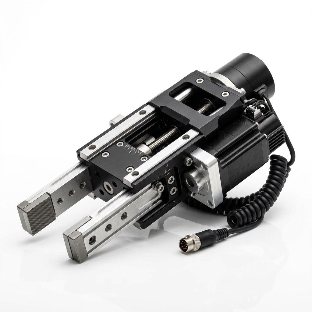
General CNC machined servo gripper finger reference showing carrier geometry and mounting interfaces. This product image does not demonstrate battery qualification, dielectric testing, or measured particle performance.
For high-speed transfer nests and multi-cell spacing grippers, explore our EOAT machining tolerance standards and material selection guide for robot grippers.
7. Material Selection Matrix: Polymers, Ceramics, and Non-Ferrous Metals
Choose materials by function, then request grade-specific evidence. A small-sample dielectric-strength value in kV/mm must not be multiplied by pad thickness to claim a safe working voltage for an assembled tool.
| Material Class & Grade | Candidate Role in Battery EOAT | Electrical Function | Evidence to Request | Cu/Zn/Ni Review | Key Engineering Limitation |
|---|---|---|---|---|---|
| Virgin PEEK (Unfilled) | Insulating jaw faces and spacers | Insulating candidate; grade-specific qualification | CTI, dielectric test conditions, conditioning, wear data | Declare resin, pigments, and additives | Cost, creep, and machining stress; verify assembled insulation. |
| POM-ESD (Carbon-Filled) | Static-dissipative pads where electrically permitted | Dissipative; not a high-voltage barrier | Surface/volume resistance and grounding requirements | Declare conductive filler and additives | Must not bridge potentials or replace the insulating pad. |
| PEI (Unfilled) | Insulating spacers and temperature-sensitive nests | Insulating candidate; grade-specific qualification | CTI, temperature, solvent compatibility | Declare grade and additives | Verify cleaning compatibility and mechanical stress. |
| Zirconia Ceramic (ZrO2) | Locating pins and bushings | Insulating candidate; verify actual ceramic grade | Electrical properties, fracture data, fit inspection | Declare composition and processing residues | Brittle; check bending, impact, and retention. |
| 6061-T6 Aluminum | Carrier, adapter plate, manifold | Conductive structural member | Material certificate and coating declaration | Contains Cu; assess against agreed limits | Anodizing alone is not the qualified isolation barrier. |
| AISI 316L Stainless Steel | Fasteners, pins, pneumatic hardware | Conductive structural member | Material certificate, passivation and wear records | Contains Ni; requires an accepted exception | Mass, galling, and particle release need review. |
8. Contamination Risk and Surface Treatment Matrix
Standard industrial surface finishes frequently introduce trace metal particulates. Tooling procurement specifications must explicitly dictate approved base metals and chemical finishes.
| Industrial Surface Finish | Base Substrate | Contamination Risk Profile | Battery Cleanliness Status | Recommended Replacement Specification |
|---|---|---|---|---|
| Electroless Nickel | Steel / Aluminum | Coating wear can release Ni-bearing particles. | Customer approval required; F1A lists an exception | Review coating integrity and exposure zone; use an accepted alternative if excluded. |
| Zinc Electroplating | Steel fasteners / Brackets | Plating damage during assembly can release Zn-bearing debris. | Review against explicit Zn restrictions | Consider an approved unplated fastener grade and corrosion plan. |
| Brass / Bronze | Fittings, bushings | Cu-bearing alloys; composition and wear depend on grade. | Often unsuitable for low-Cu requirements | Request a battery-rated component declaration and approved replacement material. |
| Type III Hard Anodizing | Aluminum carrier | Coating wear, pore sealing chemistry, and substrate composition matter. | Conditional structural finish | Specify alloy, thickness, sealing chemistry, masking, and inspection; do not use as the sole insulation barrier. |
| Electropolished / Passivated 316L | Stainless steel plates / pins | Surface treatment does not remove bulk nickel or eliminate wear particles. | Requires accepted Ni exception | Specify electropolishing and/or passivation separately with a particle acceptance method. |
| Ground Ceramic | Zirconia / Alumina | Chips and abrasive residues remain possible. | Grade- and application-dependent | Specify edge condition, retention, surface finish, cleaning, and particle inspection. |
9. CNC Machining & GD&T Inspection Tolerances for EV Battery EOAT
Polymer-to-metal differential expansion can shift datums and reduce electrical spacing. The following values are illustrative RFQ discussion targets, not demonstrated shop capability or a guarantee of alignment. Confirm feasibility, inspection temperature, polymer conditioning, coating allowance, and datum references with the supplier before drawing release.
| Tooling Feature | Example Dimension Range | Drawing Requirement to Define | Illustrative RFQ Target | Inspection Tool & Protocol |
|---|---|---|---|---|
| Aluminum Carrier Pocket Datum | 50 mm to 300 mm length | Flatness 0.02 mm / Parallelism 0.02 mm | ± 0.015 mm | Coordinate Measuring Machine (CMM) multi-point scan. |
| Ceramic Dowel Pin Bores (Al Body) | Ø 4.0 mm to Ø 8.0 mm | Position with explicit datum references | H7 size limits selected for actual nominal diameter | Calibrated plug gauges plus CMM position check. |
| PEEK Insulator Expansion Slot | 10 mm to 50 mm length | Profile and datum scheme; usable travel | Calculate from differential expansion and tolerance stack | Optical CMM and conditioned-assembly travel check. |
| Fastener Counterbore Depth | Application-specific | Recess, remaining insulation, and path dimensions | Depth allowance from approved electrical and mechanical design | Depth micrometer and assembled insulation-path inspection. |
| Contact Face Planarity | 100 mm x 150 mm pad face | Flatness 0.03 mm across full span | ± 0.020 mm | Granite surface plate with dial indicator sweep. |
| Dielectric Pad Surface Roughness | Full contact surface area | Ra and lay; define Rz separately if needed | Example Ra ≤ 0.8 µm, subject to contact validation | Profilometer at agreed locations without damaging the pad. |
10. Procurement and RFQ Engineering Checklist
Before releasing drawing packages and RFQs for custom EV battery cell grippers, module assembly nests, or transfer tooling, verify that the engineering documentation includes the following requirements:
- Electrical scope: Supply the cell/can potential map for every process state, insulation function, maximum working voltage, impulse requirement, and approved assembled-tool test voltage, duration, and acceptance criteria.
- Clearance and creepage: Identify the governing standard and edition, CTI evidence, pollution degree, altitude, and worst-case paths around screws, caps, slots, wear, and tolerances. Keep POM-ESD outside the required isolation path.
- Material and particle requirements: Define Cu/Zn/Ni thresholds by constituent, component, and exposure zone; list permitted exceptions. Specify particle limits, extraction method, sampling area, and inspection report requirements separately from alloy content.
- Cell contact and retention: Provide approved contact zones, maximum deformation and force limits, measured friction assumptions, robot acceleration and emergency-stop cases, and ledge-bearing requirements.
- Dry-room conditioning: State dew point, ambient temperature, cleaning exposure, conditioning duration, and pre/post-conditioning dimensional acceptance criteria for the selected polymer grade.
- Coatings and sealing chemistry: Specify accepted substrate, coating, sealer, masking, thickness allowance, and wear inspection. Confirm any nickel-containing treatment against customer exclusions.
- Datums and fasteners: Define fit by actual nominal size, inspection temperature, and material. Keep conductive dowels and screws outside isolation boundaries; avoid damaging interference loads on ceramics.
- Pneumatic components and lubricants: Obtain component-level material, seal, lubricant, dry-room, and particle-emission declarations instead of assuming an entire product family is accepted.
- Cleaning, packaging, and traceability: Agree on compatible cleaning and drying, residual particle testing, packaging, lot identification, material certificates, and first-article inspection records.
Use this checklist to request a drawing and inspection-plan review before fixing alloy, coating, or tolerance substitutions in the purchase order.
11. Frequently Asked Questions (FAQ)
Why can't anodized aluminum be used directly as a high-voltage dielectric barrier?
Anodizing can be damaged at edges, fasteners, and sliding contacts. Do not rely on a general hard-anodize callout as the sole safety insulation. Specify a qualified insulating material and assembly geometry, then verify the required electrical performance after the agreed conditioning and wear exposure. Neither a generic coating thickness nor a universal polymer wall thickness establishes a safe working voltage.
How do you handle thermal expansion differences between aluminum and PEEK?
Use the actual stock grade's thermal expansion data over the service temperature range. For illustration, assume alpha_PEEK = 47 µm/(m·°C), alpha_Al = 23 µm/(m·°C), L = 0.100 m, and a temperature change of 15°C:
Differential growth = (47 - 23) * 0.100 * 15 = 36 µm = 0.036 mm.
These are assumed inputs, not a supplier datasheet claim. One fixed datum and one appropriately sized expansion slot can accommodate differential movement. Include machining tolerances, screw clearances, creep, and the resulting electrical path changes in the design review.
Are zirconia ceramic dowels fragile during high-speed robotic indexing?
Ceramic pins can be sensitive to impact, bending, edge damage, and installation stress. Select the grade and diameter from actual load and fracture data; do not infer a safe indexing speed from compressive strength alone. An H7/h6 pairing is a clearance fit, not a transition fit. Specify size-dependent limits, retention, and assembly procedure with the pin supplier, and inspect chips after representative cycling.
What pneumatic lubricants are permitted in battery dry rooms?
Use the actuator supplier's approved lubricant with customer acceptance for the process environment. Request composition restrictions, migration or outgassing evidence where relevant, seal compatibility, and operating particle-emission data. PFPE or PTFE formulations may be candidates, but no lubricant chemistry alone proves dry-room or cleanroom suitability; an ISO air-cleanliness class is not a universal lubricant certification.
How should custom PEEK gripper pads be cleaned on the production floor?
Use a documented process compatible with the exact polymer grade, coatings, seals, and adhesives. High-purity IPA may be suitable if approved by the relevant material suppliers and production-line owner. Define wipes, solvent purity, drying, and residue inspection; air-cleanliness classification alone does not certify a wipe or cleaning method. Inspect cleaned pads for wear and exposed fasteners before reuse.
12. Sources and References
References updated November 1, 2026. These sources establish their stated scope; the force and expansion examples above are reproducible calculations using explicitly assumed inputs. They do not establish tested cell pressure limits, universal insulation dimensions, or this supplier's qualification.
- IEC 60664-1:2020+AMD1:2025 CSV — Insulation coordination — Consolidated edition identified in the official IEC lifecycle record. Use the governing edition's full requirements to select insulation distances; the catalogue record does not validate a specific tool design.
- Festo — Products for Battery Cell Production, version 2.0, February 1, 2023 — Page 4 defines the F1A alloy-content classification and its exceptions, including nickel in steels and chemically nickel-plated surfaces. Confirm current component declarations when ordering.
- VDA QMC — Official publications catalogue, Volume 19.1 — Lists the third revised edition, February 2026, titled Inspection of Technical Cleanliness: Particulate contamination of functionally relevant automotive components. Specify the agreed inspection method and customer acceptance limits; the publication listing does not establish a blanket alloy ban.
Prepare an EV Battery EOAT RFQ
For a custom EOAT machining enquiry, include the carrier and pad drawings, electrical boundaries, cell contact limits, and required material and inspection records. Identify ceramic grinding, conditioned-polymer inspection, assembled electrical testing, and controlled packaging as separate scope items so the quotation states who performs each operation and supplies each report.
Submit your CAD drawings and battery tooling requirements with the cell model, potential map, process environment, and RFQ checklist. Request a DFM review of material availability, machining tolerances, inspection scope, and documentation. Electrical safety and cell-handling approval remain with the responsible integrator and cell manufacturer.
Author

More Posts
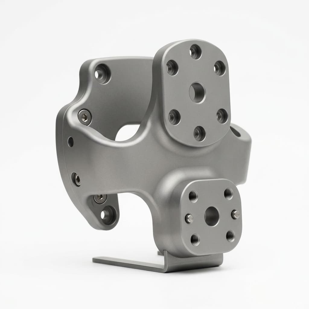
Cobot EOAT Machining: Inertia & RFQ Guide
Plan cobot EOAT machining with payload and inertia calculations, contact-edge risk checks, flange tolerances, and an RFQ checklist. Request a CAD/DFM review.
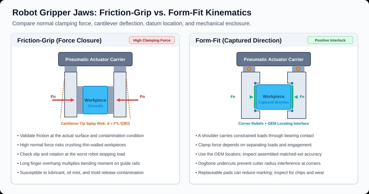
Custom CNC Machined Gripper Jaws: Form-Fit vs. Friction-Grip Engineering, Matched-Set Tolerances, and RFQ Procurement Guide
Compare custom CNC machined gripper jaws: form-fit vs friction, force sizing, matched-set tolerances, and material trade-offs. Prepare your CAD and RFQ checklist.
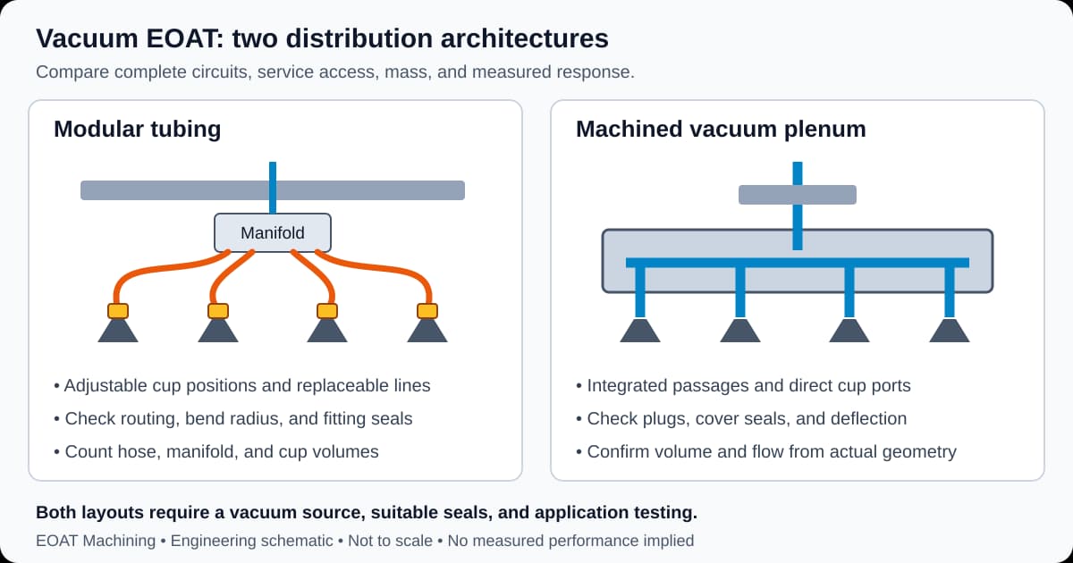
Monolithic Vacuum Plenum Plates vs. Modular Tubing in EOAT: CNC Machining, Sealing Tolerances, and Procurement Guide
Compare monolithic vacuum plenum plates vs modular tubing EOAT. Check evacuation, seal tolerances and RFQ acceptance criteria, then request a CAD review.