
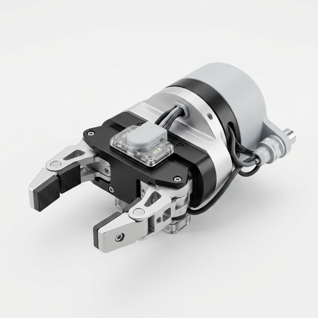
CNC Machining vs. 3D Printing for End-of-Arm Tooling (EOAT)
A comprehensive engineering comparison between CNC machining and 3D printing for robotic end-of-arm tooling, focusing on strength, tolerance, repeatability, and production scalability.
Most automation engineers eventually hit a wall: prototype grippers work fine on the bench, but fail on the production floor. The choice between 3D printing and CNC machining dictates the lifespan of your robotic cell.
TL;DR (Executive Summary): Additive manufacturing is excellent for geometry checks, early prototypes, and low-risk light payloads. CNC machining becomes the safer choice when the EOAT must survive production cycles, hold locating fits, seal vacuum channels, or ship as repeatable OEM hardware.
While additive manufacturing works for rapid prototyping, subtractive CNC machining remains the more reliable path for many industrial-grade OEM deployments. The right answer is not "always CNC" or "always print"; it depends on load, tolerance, environment, validation burden, and quantity.
Fast Decision Matrix: Print, Machine, or Hybrid?
| EOAT Requirement | 3D Printing Usually Fits | CNC Machining Usually Fits | Hybrid Strategy |
|---|---|---|---|
| Geometry proof-of-concept | Yes, especially for overnight iteration | Overkill unless geometry must be production-real | Print body, machine datum coupons |
| Production vacuum manifold | Risky for FDM due to porosity and threaded leaks | Strong fit for cross-drilled aluminum manifolds | Print geometry first, machine final manifold |
| Dowel-located jaw replacement | Poor fit without post-machining | Strong fit with reamed H7 holes and inspected datums | Print soft contact pads, machine jaw carriers |
| Food/medical washdown | Material and porosity must be validated carefully | Strong fit with 316L, passivation, cleanable surfaces | Print covers only; machine contact/washdown parts |
| Low payload gripper under test | Good fit if failure is non-critical | Good but may slow iteration | Print first 3-5 versions, machine release candidate |
| 50+ identical EOAT sets | Batch variation can become hard to control | Strong fit once CAM and inspection plan are locked | Print fixtures or cable guides; machine structural parts |
Quantity and Program Stage Matter
| Program Stage | Typical Quantity | Best Default | Why |
|---|---|---|---|
| Concept geometry check | 1-3 pieces | 3D print | Fastest way to check reach, clearance, and cup placement |
| Pilot cell trial | 3-10 pieces | Hybrid | Print non-critical covers, machine datums/manifolds/jaws |
| Customer acceptance build | 10-50 pieces | CNC machining for structural EOAT | Reduces field failure risk before factory acceptance testing |
| OEM rollout | 50-500+ pieces | CNC machining with FAI and batch inspection | Repeatability, documentation, and replacement-part consistency matter |
If you are still moving suction cups around by 10mm every day, print the prototype. If the robot program is frozen and the customer expects spare parts to fit six months later, machine the production design.
1. Material Strength & Durability (The Isotropic Advantage)
The core purpose of an end effector is to interact with the physical world—often undergoing millions of cycles under high payloads and rapid acceleration/deceleration.
Structural Integrity Analysis: CNC vs Additive
CNC Machining (Isotropic Strength)
CNC machining cuts parts from a solid billet of extruded or cast metal (such as AL6061-T6, AL7075, or Stainless Steel 304). This subtractive process preserves the continuous, isotropic grain structure of the metal.
- Result: The resulting gripper fingers or adapter plates exhibit identical tensile strength across all XYZ axes. For instance, AL7075-T6 boasts a yield strength of ~503 MPa, making it highly resistant to fatigue and impact loads during high-speed robotic collisions or emergency stops.
3D Printing (FDM/SLA/SLS)
Additive manufacturing builds parts layer by layer. While advanced materials like carbon-fiber-reinforced nylon or direct metal laser sintering (DMLS) are available, most printed parts exhibit anisotropy—they are significantly weaker along the Z-axis (the layer lines).
- The Risk: Under high shear stress, layer delamination is a common failure mode for printed polymer grippers. Even printed metals (like DMLS Aluminum) often have 10-20% lower fatigue strength than their billet counterparts due to microscopic porosity.
2. Tolerance, Precision, and Assembly Fitment
In high-speed pick-and-place applications or micro-assembly tasks, repeatability is non-negotiable. The EOAT cannot introduce positional errors into the robot's kinematic chain.
| Feature Type | CNC Machining Capability | 3D Printing Capability (FDM/SLS) |
|---|---|---|
| General Tolerance | ±0.005mm to ±0.01mm | ±0.1mm to ±0.2mm |
| Hole Diameters | Reamed to H7/G6 fits | Often requires post-drilling |
| Surface Flatness | < 0.01mm over 100mm | Prone to thermal warping |
| Thread Quality | Rigid, tapped directly | Weak, requires threaded inserts |
- CNC Machining: Capable of routinely holding tight tolerances. Machined locating pins, dowel holes, and bearing press-fits are exact, ensuring zero-backlash assembly. This is critical when mounting the tool to an ISO 9409-1 robot flange.
- 3D Printing: Even industrial printers struggle to match CNC tolerances. For precision automation, 3D printed parts often require post-machining anyway to achieve the necessary flatness for suction cup manifolds or bore diameters for pneumatic cylinders.
These numbers should be treated as drawing-dependent capability ranges, not blanket promises. A simple AL6061 plate with reamed dowel holes is very different from a tall thin-wall manifold with multiple setups. When requesting a quote, mark which dimensions are truly functional and leave cosmetic or clearance dimensions under a looser general tolerance such as ISO 2768-m.
3. Surface Finish, Cleanroom, and Vacuum Compliance
Many EOAT systems operate in specialized environments: food packaging, medical device assembly, or semiconductor cleanrooms.
Cleanroom & Food-Safe Operations
CNC machined components can be easily bead-blasted and anodized (e.g., Hard Coat Anodizing MIL-A-8625 Type III) or passivated. This seals the aluminum, prevents oxidation, and provides a smooth, non-porous surface that won't shed particulates.
Vacuum Gripping Manifolds
For vacuum EOAT, internal channels must hold the process vacuum within the cell's allowed leak rate. Machined aluminum blocks with cross-drilled and plugged channels are easier to leak-test and seal repeatably. Conversely, FDM printed parts can have porous surfaces and internal micro-voids that leak vacuum pressure, often requiring secondary epoxy sealing treatments.
Vacuum EOAT is often where the prototype-to-production gap appears. A printed manifold may prove cup placement, while a machined manifold provides predictable sealing, threaded ports, and inspection-ready datums.
4. Common Failure Modes in the Field (FMEA Perspective)
Understanding how EOAT fails is critical for high-uptime automation.
Why 3D Printed Grippers Fail:
- Layer Delamination: Sudden shear forces (like a robot crashing or misaligning during insertion) split the printed layers apart.
- Creep Under Load: Thermoplastics like ABS or PETG deform over time under constant stress. If a printed suction manifold is under constant spring tension, it may warp and lose its vacuum seal after 6 months.
- Thread Stripping: Pneumatic fittings (like M5 or G1/8 threads) screwed directly into plastic will strip if overtightened or if the pneumatic hose is repeatedly tugged.
Why CNC Machined Grippers Fail (and how to prevent it):
- Over-Tightening / Galling: Tapping stainless steel screws into aluminum can cause galling. Prevention: Use Helicoil inserts or specify hard-coat anodizing for the threads.
- Fatigue from Inertia: Using heavy solid steel blocks instead of pocketed aluminum increases the moment of inertia, eventually fatiguing the robot's servo motors. Prevention: Strategic CNC lightweighting (pocketing). (See our Material Selection Guide for Robot Grippers for optimal alloy choices).
Field note from EOAT reviews: Printed nylon suction manifolds often pass layout checks but still need leak-rate validation before production. When the design is locked, machining the manifold from AL6061 with plugged cross-drilled channels gives the buyer clearer inspection points for sealing faces, ports, and datum references.
5. Production Scalability for OEM Builders
If you are an automation integrator building a single proof-of-concept robot cell, 3D printing is fantastic. You can design a gripper on Monday and have it printing overnight.
However, if you are an OEM rolling out a standardized automation product or building dozens of work cells:
- Scalability: CNC machining scales more predictably after CAM programming, fixtures, and inspection plans are locked. The economic break point depends on geometry, setup time, material cost, finishing, and quantity.
- Supply Chain Stability: A qualified CNC partner can define dimensional inspection, material records, and repeat-order controls before batch release. Printed parts may still be useful, but batch-to-batch consistency should be validated because humidity, filament age, printer settings, and post-processing can change results.
Validation Plan Before You Release EOAT to Production
Whether you print, machine, or use a hybrid build, the buyer should validate the EOAT against the real cell conditions before release.
| Test | What It Catches | Practical Pass/Fail Signal |
|---|---|---|
| Vacuum decay test | Porous body, leaking plugs, weak O-ring compression | Vacuum drop stays within your process limit over a fixed hold time |
| Pull-off / grip force test | Cup area or jaw friction is under-sized | Safety factor remains acceptable at worst-case part weight and acceleration |
| 10k-100k dry cycle test | Creep, loose inserts, cracked printed layers, fastener loosening | No visible deformation, no TCP drift, no vacuum response change |
| Thermal soak | Warping, material creep, seal shrinkage | Fit and leak rate remain stable after expected plant temperature range |
| Jaw replacement repeatability | Poor dowel strategy or loose screw clearance | Replacement jaws return to the same datum without robot reteaching |
Ask your supplier which tests they can support and which ones you must run in your own robot cell. A machine shop can inspect dimensions and leak-test a manifold, but only the integrator can validate dynamic robot motion, payload acceleration, and part release timing.
Conclusion: Engineering Guidelines
Use 3D Printing When:
- You are rapidly prototyping a gripper design to test geometric clearances.
- The payload is extremely light (e.g., <500 grams), and strength/fatigue life is not a primary concern.
- The geometry has complex, winding internal cooling channels that cannot be reached by a standard drill bit.
Use CNC Machining When:
- The EOAT operates in a heavy-duty, high-cycle (24/7) industrial environment.
- You require rigid tolerances for precision assembly, pneumatic sealing, or micro-manipulation.
- The design is finalized and you need to manufacture reliable batches for deployment to end-users.
Use a Hybrid Strategy When:
- You want printed soft pads or covers but machined aluminum datums, brackets, or manifolds.
- You need 3D printed geometry for fast iteration but CNC machined production spares.
- You need to validate cup layout first, then lock the final manifold and jaw carriers for batch production.
Frequently Asked Questions (FAQ)
Q: Can I use 3D printing for vacuum suction grippers? A: Yes, but FDM printed parts are often porous and may leak vacuum pressure. You may need epoxy sealing or another secondary process. CNC machined aluminum manifolds with cross-drilled channels are usually easier to seal, plug, and leak-test.
Q: What is the lead time for custom CNC machined end effectors? A: Lead time depends on geometry, material availability, surface finish, inspection scope, quantity, and export destination. Simple aluminum prototypes can move quickly, while finished production batches need more planning.
Q: Does CNC machining limit the complexity of my gripper design? A: CNC machining (especially 5-axis milling) can produce incredibly complex geometries. However, internal right-angle corners and fully enclosed internal voids are the primary limitations compared to 3D printing.
At EOAT Machining, we specialize in translating custom end effector designs into high-performance CNC machined reality. If you have a locked CAD model and need a reliable OEM manufacturing partner, reach out to our engineering team today for a DFM review and quotation.
Author

Categories
More Posts
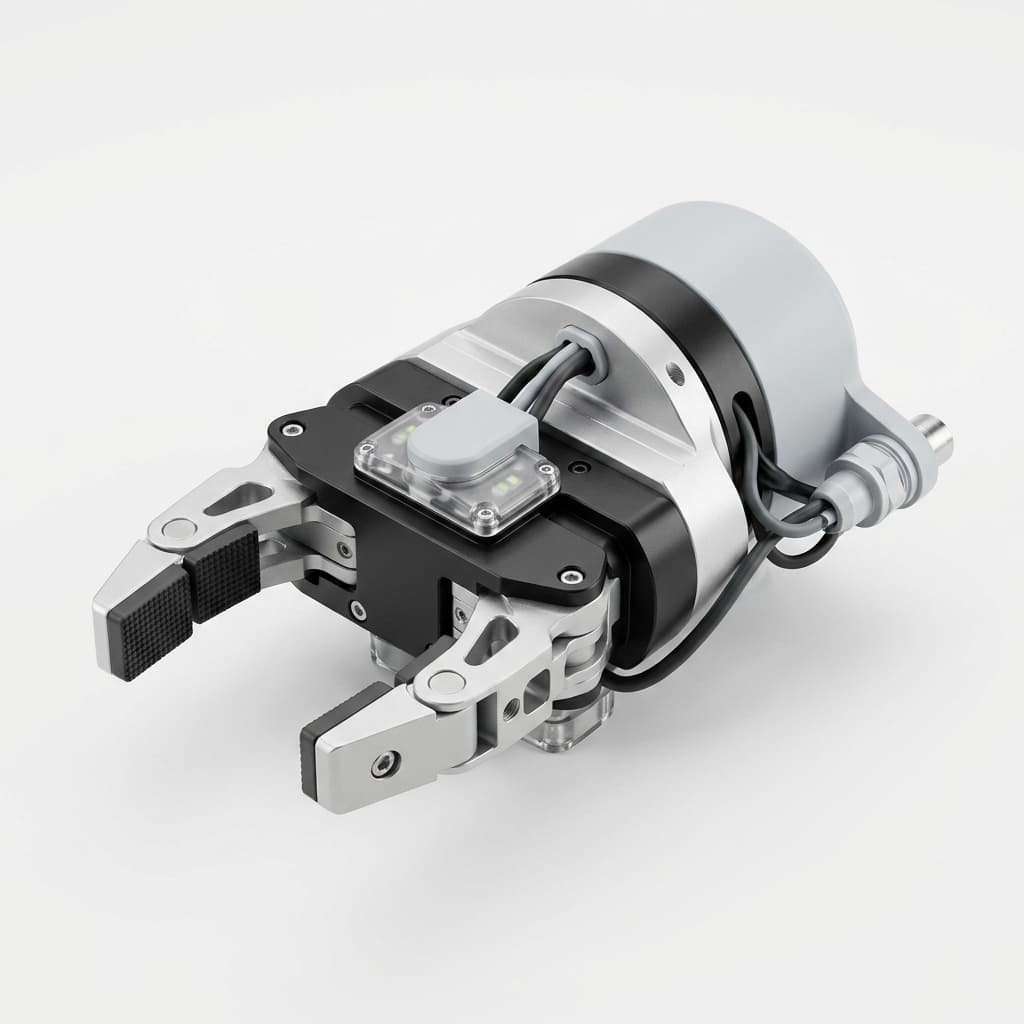
Custom CNC Machining for AI Vision-Guided EOAT: Calibration Stability and Procurement Guide
Prevent hand-eye calibration drift in vision-guided EOAT with CNC machined camera mounts, DFM rules, tolerance notes, and an RFQ checklist.
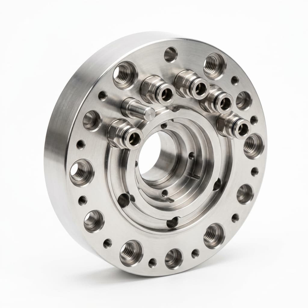
Robotic Automatic Tool Changers (ATC): Machining Tolerances and Procurement Specs for EOAT
Specify robotic Automatic Tool Changers for EOAT machining: repeatability, fail-safe locks, utility ports, payload moments, and supplier QA checks.
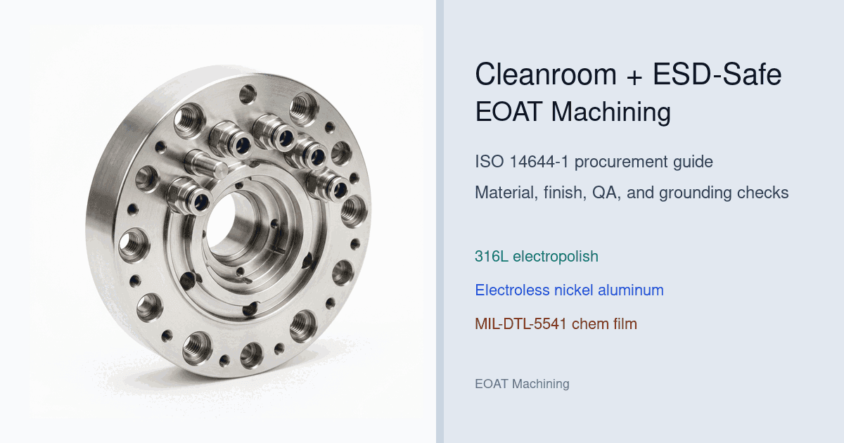
Cleanroom & ESD-Safe EOAT Machining: ISO 14644-1 Procurement Guide
Procurement guide to specify cleanroom and ESD-safe EOAT machining for ISO 14644-1 cells: compare finishes, risks, QA checks, and request DFM support.