
5-Axis Machined EOAT Bracket: Sizing Tool & DFM Guide
Screen estimated bracket mass, bending moment and machining approach. Review assumptions, then request a drawing-based DFM quote.
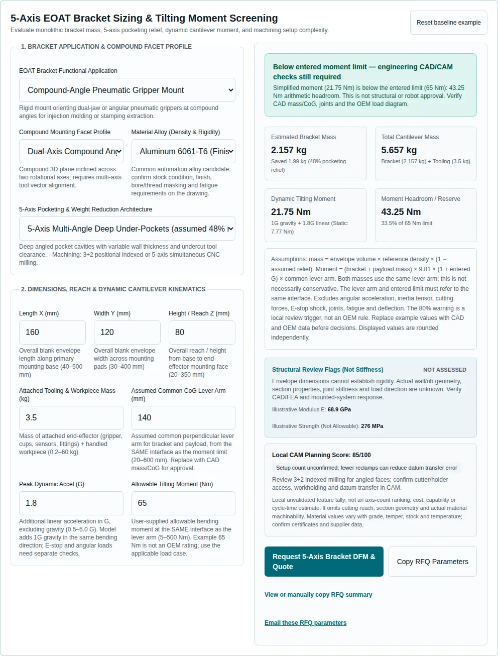
5-Axis EOAT Bracket Sizing & Tilting Moment Screening
Evaluate monolithic bracket mass, 5-axis pocketing relief, dynamic cantilever moment, and machining setup complexity.
- Estimated Bracket Mass
- 2.157 kg
- Saved 1.99 kg (48% pocketing relief)
- Total Cantilever Mass
- 5.657 kg
- Bracket (2.157 kg) + Tooling (3.5 kg)
- Dynamic Tilting Moment
- 21.75 Nm
- 1G gravity + 1.8G linear (Static: 7.77 Nm)
- Moment Headroom / Reserve
- 43.25 Nm
- 33.5% of 65 Nm limit
Assumptions: mass = envelope volume × reference density × (1 − assumed relief). Moment = (bracket + payload mass) × 9.81 × (1 + entered G) × common lever arm. Both masses use the same lever arm; this is not necessarily conservative. The lever arm and entered limit must refer to the same interface. Excludes angular acceleration, inertia tensor, cutting forces, E-stop shock, joints, fatigue and deflection. The 80% warning is a local review trigger, not an OEM rule. Replace example values with CAD and OEM data before decisions. Displayed values are rounded independently.
Envelope dimensions cannot establish rigidity. Actual wall/rib geometry, section properties, joint stiffness and load direction are unknown. Verify CAD/FEA and mounted-system response.
Review 3+2 indexed milling for angled faces; confirm cutter/holder access, workholding and datum transfer in CAM.
Local unvalidated feature tally; not an axis-count ranking, cost, capability or cycle-time estimate. It omits cutting reach, section geometry and actual material machinability. Material values vary with grade, temper, stock and temperature; confirm certificates and supplier data.
View or manually copy RFQ summary
Executive Engineering Summary: 5-Axis Monolithic EOAT Brackets
Fewer internal joints
A monolithic body can remove intermediate joints. Base/tool joints, elastic deflection and fatigue still require checks.
Evidence and scope: VDI 2230 Part 1:2015 — Calculation of highly stressed bolted joints
Assumed mass relief
25%, 48% and 65% are what-if presets. Actual removed volume and stiffness must be established from the design.
Evidence and scope: NASA CR-124075 — Isogrid Design Handbook (1973)
Confirm datum capability
Indexed machining can reduce reclamping. Confirm workholding, tolerance and inspection rather than assuming zero error.
Evidence and scope: Haas — G234 Tool Center Point Control (TCPC) · ASME Y14.5-2018 (R2024) — Dimensioning and Tolerancing
1. Monolithic 5-Axis vs. Stacked Multi-Piece Angle Brackets
A bracket positions individual tools or sensors; a wrist adapter plate matches the robot flange interface. A custom bracket body can integrate several angled pads and remove intermediate adjustment joints. It still has mounting fasteners and elastic compliance. A modular assembly can be the better choice when frequent adjustment, low initial cost or replaceable wear parts matter. Compare total setup, inspection, maintenance and spare-part cost rather than assuming a monolithic part is always cheaper or safer.
| Decision | Stacked / modular | Monolithic | Required check |
|---|---|---|---|
| Adjustment | Easy to reconfigure | Machined angle is fixed | Prototype the orientation before committing |
| Load path | Multiple clamped interfaces | Fewer internal interfaces | Verify slip, preload, stress and fatigue for both |
| Accuracy | Datum transfers and adjustment affect alignment | Fewer transfers may help | Part-specific datum and inspection plan |
| Cost / repair | Standard parts and local replacement may reduce initial cost | Custom CAM, stock removal and whole-part replacement may cost more | Quote quantity, setup, scrap and spares |
| Clearance | Fastener and adjuster envelopes matter | Integrated geometry may reduce envelope | Check robot path and holder access in CAD/CAM |
Compare load paths and interface count. Both designs need joint and body-compliance checks; no measured drift or guaranteed rigidity is shown. Schematic; not a manufacturing drawing. Scroll the diagram on small screens.
Evidence and scope: ASME Y14.5-2018 (R2024) — Dimensioning and Tolerancing · Haas — G234 Tool Center Point Control (TCPC)
2. Dynamic Cantilever Moments, Inertia & Acceleration Mechanics
This tool is a one-plane what-if model. It applies gravity and additional linear acceleration in the same bending direction, with bracket and payload mass at one common lever arm. The lever arm and entered allowable moment must use the same interface. A bracket-base result cannot be compared directly with a wrist rating if their reference locations differ.
M_static = (m_bracket + m_tooling) × g × L_CG
M_dynamic = (m_bracket + m_tooling) × (g + a_dynamic) × L_CG
Point-mass illustration only: J = Σ(m × r²); CAD body inertia is also required
For the same material distribution approximated as point masses, removing 0.5 kg at 0.2 m changes J by 0.020 kg·m², equal to 2 kg at 0.1 m. Real bodies also have inertia about their own centres. Angular acceleration, cutting loads, E-stop shock and joint stresses are excluded. Use CAD mass properties, vectors and the robot OEM load diagram; the common-arm estimate can be high or low.
Illustrative one-plane lever arm. The calculator places both masses at the same arm and adds gravity to entered linear acceleration; E-stop and angular loads are excluded. Schematic; not a manufacturing drawing. Scroll the diagram on small screens.
Evidence and scope: ISO 9409-1:2004 — Robot mechanical interfaces: Plates · thyssenkrupp — Aluminum alloy and temper availability
3. 5-Axis Pocketing Architectures: Solid vs. Perimeter vs. Isogrid Webbing
Pocketing trades mass against section stiffness, fatigue detail, machining time and cleaning access. Integral triangular ribs are one option described in NASA CR-124075, but the handbook does not validate this bracket. The tool presets only remove an assumed fraction of envelope volume. Confirm retained geometry, mass and load paths in CAD/FEA before selecting a pocket style.
| Architecture | Assumed removed volume | Stiffness evidence | Manufacturing / tradeoff |
|---|---|---|---|
| Solid | 0% | Unknown without geometry / joints | Baseline mass only; may consume payload |
| Shallow pockets | 25% | Unknown; section location matters | Compare 3-axis setups and finishing access |
| Angled deep pockets | 48% | Unknown; local ribs and corners need FEA | Indexed or continuous access subject to CAM |
| Isogrid | 65% | Unknown; NASA handbook is not bracket validation | Thin ribs can increase machining, inspection and cleaning effort |
The 65% relief is an assumed what-if preset. Retained stiffness is unknown without the actual rib geometry and load case. Schematic; not a manufacturing drawing. Scroll the diagram on small screens.
Evidence and scope: NASA CR-124075 — Isogrid Design Handbook (1973) · Haas — G234 Tool Center Point Control (TCPC)
4. Compound-Angle Geometry: 3+2 Positional Indexing vs. Continuous 5-Axis Milling
Accessible planar pads can often be machined with indexed 3+2 positioning. Continuous tool-vector changes may favor simultaneous five-axis milling. Ribbing alone does not prove a need for continuous motion. CAM must verify tool and holder clearance, rotary travel, workholding, datum transfer and access to every feature.
DWO compensates work-offset changes for indexed positioning; TCPC supports tool-point control during simultaneous motion. Neither establishes part capability. Request a setup plan and inspection evidence for the actual datum scheme.
Indexed position shown: the selected facet is horizontal under the vertical spindle. The actual rotary pose depends on the CAD face and machine configuration. Schematic; not a manufacturing drawing. Scroll the diagram on small screens.
Evidence and scope: Haas — G234 Tool Center Point Control (TCPC) · ASME Y14.5-2018 (R2024) — Dimensioning and Tolerancing
5. Material Selection Matrix: 6061-T6 vs. 7075-T651 vs. Stainless vs. Titanium vs. Polymers
These are illustrative nominal constants shared with the calculator, not certified design allowables. Strength depends on temper, heat treatment, stock size, temperature and test method. Polymer values are grade-dependent tensile references. No fatigue life or strength acceptance is calculated. Obtain supplier data and material certificates before design release.
| Material / condition | Density g/cm³ | Modulus GPa | Strength reference MPa | Selection boundary |
|---|---|---|---|---|
| 6061-T6 | 2.70 | 68.9 | 276 | Confirm temper, thickness and coating |
| 7075-T651 | 2.80 | 71.7 | 503 | Higher nominal strength; similar modulus to 6061 |
| 304 stainless | 7.93 | 193 | 215 | Higher mass; confirm chemical compatibility |
| 316L stainless | 8.00 | 193 | 220 | Grade/finish alone does not qualify hygiene |
| 4140 pre-hardened | 7.85 | 205 | 655 | Strength depends strongly on heat treatment |
| Ti-6Al-4V | 4.43 | 114 | 880 | Cost and machinability need review |
| POM-C | 1.41 | 2.8 | 65 | Grade-specific tensile reference; creep not modeled |
| PEEK unfilled | 1.32 | 4.0 | 100 | Grade-specific tensile reference; qualification not inferred |
Thermal Expansion Drift (CTE) & Diurnal Shop Floor Precision Limits
Thermal growth is calculated here only for a uniformly heated, freely expanding 200 mm member: ΔL = α × L × ΔT. The CTE values are stated assumptions for comparison and must be checked for the actual grade and temperature. Restraints, gradients, joints and mixed materials change alignment. At assumed α = 23.4 µm/(m·°C) and ΔT = 15°C, growth is 70.2 µm, exceeding a 25 µm alignment budget.
| Material | Assumed CTE µm/(m·°C) | ΔT 10°C | ΔT 20°C | ΔT 30°C |
|---|---|---|---|---|
| 6061 | 23.4 | 46.8 µm | 93.6 µm | 140.4 µm |
| 7075 | 23.6 | 47.2 µm | 94.4 µm | 141.6 µm |
| 316L | 16.0 | 32.0 µm | 64.0 µm | 96.0 µm |
| 4140 | 12.2 | 24.4 µm | 48.8 µm | 73.2 µm |
| Ti-6Al-4V | 8.6 | 17.2 µm | 34.4 µm | 51.6 µm |
| POM-C | 110 | 220 µm | 440 µm | 660 µm |
Evidence and scope: thyssenkrupp — Aluminum alloy and temper availability · Outokumpu — Supra stainless range
6. GD&T Datum Reference Frames Across Compound Faces (ASME Y14.5-2018)
Dimensioning compound-angle EOAT brackets without an unambiguous datum reference frame (DRF) leads to inspection disputes and assembly misfits. Define functional datum features and their reference frame using a coherent drawing standard.
An illustrative scheme uses base contact A, a locating feature B and a clocking feature C. The designer selects flatness, fit, position and surface-profile controls from function. The example diagram is not a factory tolerance promise. ISO 10791-7 machine-test evidence and ISO 10360-2 CMM performance checks serve different purposes; neither replaces part acceptance.
Primary datum face A, primary dowel B, clocking dowel C, with basic angles locating compound tooling pads under a single coordinate frame. Schematic; not a manufacturing drawing. Scroll the diagram on small screens.
Dowel Pins: Separate Product Specification from Joint Capacity
ISO 8734 specifies the dowel product, not a universal EOAT load rating. Check the pin and parent material for shear, bending, bearing, fit, tear-out and fatigue. Nominal projected bearing stress is F/(d × t), with N and mm giving MPa. The comparison below uses assumed F = 1,000 N and t = 10 mm; acceptance is unknown until an appropriate allowable and all failure modes are checked.
| Diameter d | Assumed engagement t | Assumed force F | F/(d × t) | Acceptance |
|---|---|---|---|---|
| 4 mm | 10 mm | 1,000 N | 25.0 MPa | Unknown: check pin, parent material, edge ligament and fatigue |
| 6 mm | 10 mm | 1,000 N | 16.7 MPa | Unknown: check fit, bending and shear plane count |
| 8 mm | 10 mm | 1,000 N | 12.5 MPa | Unknown: verify parent material bearing allowable |
| 10 mm | 10 mm | 1,000 N | 10.0 MPa | Unknown: verify load sharing and tear-out |
| 12 mm | 10 mm | 1,000 N | 8.3 MPa | Unknown: ISO 8734 is not an assembly rating |
Nominal projected bearing stress is F/(d × t). Pin shear, fit, parent material and edge tear-out require separate checks; no safe load is established. Schematic; not a manufacturing drawing. Scroll the diagram on small screens.
Evidence and scope: ASME Y14.5-2018 (R2024) — Dimensioning and Tolerancing · ISO 22081:2021 — General geometrical and size specifications · ISO 8734:1997 — Hardened steel and martensitic stainless dowel pins · ISO 10791-7:2020 — Accuracy of finished test pieces
7. Optical Vision & 3D Sensor Mounts: Deflection, Vibration Damping & Repeatability
Camera motion tolerance depends on field of view, pixel scale, exposure and the inspection task. Bracket flexibility, joints, robot pose and trajectory can all affect blur and settling. Specify a measurable optical acceptance criterion; envelope dimensions alone cannot establish it.
Gussets can change stiffness and modes. Confirm the mounted camera response; this schematic predicts no frequency or settling time. Schematic; not a manufacturing drawing. Scroll the diagram on small screens.
Structural Natural Frequency (fn) vs. Robot Closed-Loop Servo Bandwidth
Controller update rate, servo bandwidth and structural natural frequency are different quantities. None is supplied by this tool. There is no universal 75 Hz safe threshold or guaranteed settling time. Obtain mounted-system modes and excitation data, then validate the intended path and image acquisition timing. Geometry changes, a shorter reach or motion smoothing are candidates for testing.
| Question | Required evidence | Unknown in this tool | Next step |
|---|---|---|---|
| What excites the structure? | Actual path acceleration/jerk spectrum | Controller / trajectory excitation | Obtain robot/OEM motion data |
| Which modes participate? | Mounted assembly modal model or test | Mode frequencies, directions and damping | Include camera, joints and robot pose |
| How long does ringing persist? | Measured response at exposure timing | Damping and settling time | Measure the intended motion / acquisition sequence |
| Is the image stable? | Pixel scale, exposure, blur tolerance | Allowable sensor motion | Test optical acceptance; shorten reach or revise ribs if needed |
Qualitative schematic only; curves are not measured data and their positions have no numerical scale. Compare actual excitation, modes and damping before judging settling. Schematic; not a manufacturing drawing. Scroll the diagram on small screens.
Evidence and scope: thyssenkrupp — Aluminum alloy and temper availability · ASME Y14.5-2018 (R2024) — Dimensioning and Tolerancing · ISO 9409-1:2004 — Robot mechanical interfaces: Plates
8. High-Shock Tooling: Sprue Degating Nippers & Cutting Reaction Forces
Cutting or pneumatic reaction loads can dominate inertial loads and are not included in the calculator. Obtain force-time data from the tool supplier or measurement, resolve force and moment at the actual interface and check fasteners, contact slip, dowels and fatigue. A monolithic body does not remove these checks. Use a separate supported cutter when wrist loads or positioning requirements make a cantilever unsuitable.
A cutting reaction adds loads absent from the calculator. Trace the load through body, fasteners and locating features using tool-specific force data. Schematic; not a manufacturing drawing. Scroll the diagram on small screens.
Evidence and scope: thyssenkrupp — Aluminum alloy and temper availability
9. Integrated Cable Management, Pneumatic Galleries & Dowel Pin Bores
Recessed routing can reduce snag exposure, but check minimum cable bend radius, moving clearance, drainability, access for cleaning and remaining wall thickness. Internal pneumatic galleries need agreed pressure/leak tests and plug details. Compare external serviceable tubing where enclosed passages would complicate maintenance.
Check cable bend radius and clearance. Dowel fit and datum control support repeatability but require an assembly-specific tolerance plan. Schematic; not a manufacturing drawing. Scroll the diagram on small screens.
VDI 2230 Bolted Joint Reliability & Thread Shear in Light Alloys
Check both tightening and service loads in the actual joint. Effective engagement, parent material, bolt grade, friction, preload scatter and boss geometry determine stripping and fatigue resistance. This page does not prescribe a universal engagement ratio or tightening torque. Inserts can support serviceability, but their capacity and installation need manufacturer data and a joint calculation.
| Joint issue | Inputs to confirm | Review method / alternative |
|---|---|---|
| Internal stripping | Thread pitch, tolerances, effective length, parent strength | Calculate stripping resistance and boss failure |
| Preload | Bolt grade, friction, coating, installation scatter | Check assembly preload range and joint separation |
| Fatigue / slip | Load cycle, load sharing, stiffness, contact surfaces | Apply the relevant VDI 2230 method and verify installation |
| Insert selection | Parent boss, insert series/length and installation | Use manufacturer data; test if qualification requires it |
| Service changeover | Inspection and replacement policy | Compare replaceable bushings, inserts or a modular pad |
Both direct threads and inserts need stripping, boss, preload and fatigue checks. The insert is an option, not proof of a safe failure mode. Schematic; not a manufacturing drawing. Scroll the diagram on small screens.
Evidence and scope: VDI 2230 Part 1:2015 — Calculation of highly stressed bolted joints · Böllhoff — HELICOIL thread inserts · ISO 8734:1997 — Hardened steel and martensitic stainless dowel pins
10. Surface Finishing: Mil-A-8625 Type III Hard Anodize, Electropolish & Passivation
Select finish against operating chemistry, wear, dimensional fit and inspection requirements. Specify which datums, dowel bores and threads are masked or finished to final size after coating. No coating thickness, hardness, salt-spray result or hygiene approval is guaranteed here; agree acceptance evidence with the supplier.
| Candidate process | Specify | Main risk | Acceptance evidence |
|---|---|---|---|
| Hard anodizing | Alloy, coating type, thickness, sealing and masking | Bore/thread size changes, edge buildup, fatigue effects | Agreed coating and post-finish dimensional report |
| Decorative anodizing | Color, alloy, surface prep and masking | Color variation and wear mismatch | Approved sample and finish specification |
| Electropolish / passivation | Grade, starting finish, required Ra and cleaning chemistry | Material removal and crevice retention | Measured surface and agreed process records |
| Electroless nickel | Substrate condition, deposit type, thickness and masking | Tolerance growth and uneven access in recesses | Coating verification and final inspection |
Evidence and scope: thyssenkrupp — Aluminum alloy and temper availability · Outokumpu — Supra stainless range
11. Tool Reach, Cutter Deflection, and DFM Guidelines in Deep 5-Axis Pockets
Designing deep pockets or steep undercut walls without considering cutter reach leads to tool chatter, tapered walls, and tool holder collisions. 5-axis machining allows tilting the cutter to utilize stub-length tooling, but proper internal corner radii and wall thicknesses remain critical DFM rules:
- Review corner radius, depth, cutter diameter and holder access together; no single radius/depth ratio proves machinability.
- Retained walls and ribs need workholding, cutting-force, distortion and structural checks. A minimum thickness cannot be assigned from material name alone.
- Show effective thread depth, breakout risk and insert requirements on the drawing; confirm them using the actual joint calculation.
Tilting may shorten tool reach. Verify clearance and cutting stability for the actual machine, holder, fixture and workpiece. Schematic; not a manufacturing drawing. Scroll the diagram on small screens.
Cutter Overhang Ratio (L/D) & Harmonic Deflection Mechanics
For an ideal cantilever with constant force F, modulus E and section I, δ = F × L³/(3 × E × I). Doubling reach gives 8× total deflection, a 700% increase. The table normalizes to L/D = 3 for the same diameter. Flutes, holder compliance, force direction and dynamic cutting change the actual result. Tilting can improve access but does not guarantee chatter, tolerance or roughness.
| L/D | Relative deflection (L/3D)³ | Known limitation | Decision |
|---|---|---|---|
| 3 | 1.00× | Ideal cantilever, constant diameter | Check actual cutter and holder |
| 4 | 2.37× | Does not predict chatter or Ra | Review tool stiffness and cutting strategy |
| 6 | 8.00× | 8× total = 700% increase | Compare reduced force or better access |
| 8 | 18.96× | No guaranteed tolerance from L/D | Verify in CAM and trial cut |
For equal force, E and section, deflection scales with reach cubed. Relative values use L/D = 3 as baseline. These are different access geometries; tilting does not make an unchanged deep slot accessible. No finish or chatter prediction is made. Schematic; not a manufacturing drawing. Scroll the diagram on small screens.
Evidence and scope: Haas — G234 Tool Center Point Control (TCPC) · ISO 10791-7:2020 — Accuracy of finished test pieces
12. Calculated Engineering Sizing Scenarios
These five hypothetical examples are calculated from the same model, not measured case studies. The complete numeric inputs are shown for reproduction. They do not establish structural, hygiene or robot load acceptance.
Scenario 1: Automotive Injection Molding Demold Bracket
Below entered limit onlyPremise: Monolithic 6061-T6 bracket mounting a dual-jaw sprue gripper at 25° tilt and 15° skew for mold clearance. 48% pocketing relief is assumed; mass is computed below.
Inputs: 160 × 120 × 80 mm; payload 3.5 kg; common arm 140 mm; additional acceleration 1.8 G; entered limit 65 Nm.
2.157 kg
5.657 kg
21.75 Nm
43.25 Nm
DFM Recommendation: Confirm CAD tool path clearance inside tight mold tie-bars and verify pneumatic line clip recesses.
Scenario 2: High-Speed Battery Cell Stacking Vision Camera Bracket
Below entered limit onlyPremise: 7075-T651 aviation alloy with 65% isogrid rib webbing. Rib geometry and vibration response are unverified in this hypothetical 2.5G example.
Inputs: 180 × 100 × 90 mm; payload 1.8 kg; common arm 120 mm; additional acceleration 2.5 G; entered limit 45 Nm.
1.588 kg
3.388 kg
13.96 Nm
31.04 Nm
DFM Recommendation: Verify mounted-system modes, excitation and exposure-time settling against the actual optical acceptance criterion.
Scenario 3: High-Shock Sprue Degating Bracket
overloadPremise: 4140 steel is a hypothetical material candidate with 25% assumed relief. Heat treatment, actual strength, shock loads and fatigue resistance require separate verification; this model does not assess them.
Inputs: 220 × 150 × 110 mm; payload 12.0 kg; common arm 220 mm; additional acceleration 2.0 G; entered limit 180 Nm.
21.372 kg
33.372 kg
216.07 Nm
-36.07 Nm
DFM Recommendation: The calculated moment exceeds the entered limit by 36.07 Nm. Reduce mass or lever arm and recheck the interface rating before proceeding. Obtain cutting/shock loads separately; calculate the actual fastener, dowel and parent-material limits.
Scenario 4: Cleanroom Medical Packaging Vacuum Cup Bracket
Below entered limit onlyPremise: 316L is a hypothetical candidate for the stated cleaning environment. 48% relief is assumed; chemistry, finish and cleanability need confirmation.
Inputs: 140 × 90 × 60 mm; payload 1.5 kg; common arm 110 mm; additional acceleration 1.5 G; entered limit 35 Nm.
3.145 kg
4.645 kg
12.53 Nm
22.47 Nm
DFM Recommendation: Agree drainability, crevice control, cleaning chemistry and measured finish with the integrator; no hygiene compliance is established.
Scenario 5: Titanium Tandem-Tool Bracket Candidate
Below entered limit onlyPremise: Ti-6Al-4V is a hypothetical candidate with 65% assumed relief. At equal envelope and relief it is heavier than 6061-T6 (1.919 kg vs 1.169 kg); reduced mass requires a separately validated smaller section. No robot payload, inertia or safety approval is established.
Inputs: 150 × 110 × 75 mm; payload 2.5 kg; common arm 130 mm; additional acceleration 1.2 G; entered limit 40 Nm.
1.919 kg
4.419 kg
12.4 Nm
27.6 Nm
DFM Recommendation: Review high-speed 5-axis tool path simulation to avoid cutter tool deflection during titanium pocketing.
Reproduce the baseline screening example
Captured from this calculator on 2026-11-07: 6061-T6, 160 × 120 × 80 mm, 48% assumed relief, 3.5 kg attached mass, 140 mm common lever arm, 1.8 G additional acceleration and a 65 Nm entered limit. The result is 2.157 kg estimated bracket mass and 21.75 Nm simplified moment. Reset the calculator to reproduce it. This is software execution evidence; it does not demonstrate physical testing, customer results or approval of a manufactured bracket.
13. Authoritative Standards, Scope & Engineering Evidence
Published ; reviewed . Maintained by EOAT Machining. Next review by , or sooner when sources, model assumptions or manufacturing guidance change. Publisher pages establish the scopes below. Public summaries do not validate numerical design allowables or this factory’s capability. Calculations, relief presets, material constants and thermal examples are explicitly stated assumptions. Confirm applicable editions and full requirements for each project.
Drawing language for datums and geometric tolerances. Does not establish this factory’s capability or guarantee a part tolerance.
Interface dimensions and designation; not robot payload, bending-moment or inertia approval. Bracket-base and wrist interfaces can differ.
General specification framework. Critical features need explicit drawing controls and a coherent GPS scheme.
Design analysis of integral triangular stiffeners. It does not verify this tool’s 25%, 48% or 65% relief presets or a bracket stiffness-retention percentage.
Publisher overview of the joint-calculation method. Engagement, preload, fatigue and stripping resistance require the actual joint inputs and full applicable method; no universal 2D/2.5D minimum is claimed.
Pin product specification. It does not supply a universal aluminum bearing allowable, shear load rating or safe edge distance for an EOAT assembly.
Machine cutting-accuracy tests, including a freeform test piece for five-axis machines. Test results do not certify every bracket’s pad angle, surface finish or tolerance.
Manufacturer product guidance; select the insert, parent material, engagement and installation process from the applicable technical data. Insert selection alone does not prove joint capacity.
Control features for coordinate compensation in multi-axis work. Fewer reclamps can reduce datum transfer, but calibration, workholding and cutting errors remain.
Lists alloys and tempers; does not substantiate every mechanical constant below. Density/modulus/strength values in this tool are illustrative nominal inputs, not certified design allowables.
Grade and corrosion-selection context for the 316 family. Compatibility depends on chemistry, temperature and finish; it is not a blanket cleanroom or washdown approval.
Applies to Cartesian CMMs using contacting probes in discrete-point mode. Continuous scanning and optical systems need their applicable verification methods; this is not part acceptance by itself.
14. Frequently Asked Questions (Technical & Procurement)
Detailed engineering answers to 24 frequent questions covering 5-axis EOAT bracket design, kinematics, GD&T tolerancing, bolted joint mechanics, materials, and RFQ submission:
Kinematics and Structural Sizing
Why consider a monolithic 5-axis bracket instead of stacked parts?↓
It can remove intermediate adjustment joints and combine compound pads. Base and tool fasteners still need preload and slip checks, and the body still deflects. Compare a validated modular assembly when adjustability or low replacement cost matters.
How is the moment calculated?↓
The tool multiplies estimated bracket-plus-payload mass by 9.81 × (1 + entered acceleration in G) × the common perpendicular lever arm in metres. Both masses are placed at the same assumed distance. Use actual CAD mass properties and load vectors for approval.
Does isogrid pocketing guarantee stiffness after mass reduction?↓
No. The 25%, 48% and 65% relief values are local what-if assumptions. NASA CR-124075 explains triangular stiffeners but does not validate these bracket presets. Actual mass, section stiffness, fatigue and access need CAD/FEA/CAM checks.
What safety factor should be used?↓
No universal factor is supplied. The responsible engineer selects yield, fatigue, shock and joint margins for the robot, duty cycle and failure consequences. The 80% tool warning is only a local review trigger; it is not a safety factor.
What natural frequency prevents camera jitter?↓
There is no universal safe frequency. Check the mounted robot/tool modes, excitation spectrum, damping, exposure time and required pixel stability. Use modal analysis and settling measurements on the intended trajectory; this calculator does not predict frequency.
5-Axis Machining and GD&T
Does a compound mounting angle require simultaneous 5-axis milling?↓
Not by itself. Indexed 3+2 machining can suit accessible planar pads. Continuous tool-vector changes can favor simultaneous milling. Undercuts, holder clearance, fixturing and machine travel decide feasibility in CAM.
What positional tolerance can be quoted across angled faces?↓
It must be agreed from the drawing, datums, material, size, workholding and inspection plan. A single setup can reduce datum transfer but does not guarantee 0.02 mm or eliminate machine and cutting errors.
How should bracket datums be selected?↓
Use the functional base contact as a candidate primary datum, with locating and clocking features chosen to match assembly constraints. ASME Y14.5 defines the drawing language. The designer must specify the actual tolerance scheme.
What does ISO 10791-7 establish?↓
It specifies tests using finished test pieces to assess machine cutting accuracy. It does not give a universal bracket capability guarantee. Request relevant machine-test evidence and a part-specific inspection plan.
How are angled pads inspected?↓
Establish the drawing datum frame, measure the pad surface and locating features, and report profile or location against that frame. ISO 10360-2 concerns discrete-point contacting Cartesian CMM performance; scanning and optical methods require the applicable verification standards.
Fasteners, Dowel Shear & Thread Engagement
Why check aluminum internal threads separately?↓
The parent thread can strip before the selected bolt reaches its target preload. Check parent material condition, effective thread engagement, pitch, boss geometry, friction and the service load. VDI 2230 provides a joint-calculation framework.
Does VDI 2230 impose a universal 2D or 2.5D engagement?↓
No such universal minimum is used here. Determine effective engagement for the specific bolt grade, parent material, tolerances, preload and load cycle. Depth ratios alone cannot prove stripping or fatigue resistance.
When should wire thread inserts be considered?↓
Consider them for repeated service, wear or a calculated strength need. Select the insert length and installation method from manufacturer data and verify the parent boss. Inserts do not automatically make a shallow hole safe.
Does an ISO 8734 pin have a universal shear rating?↓
No assembly load rating is inferred here. Check pin specification, shear plane count, bending, fit, bearing stress and parent material. Nominal projected bearing stress is F/(d × t); compare with a justified design allowable.
What dowel edge distance is safe?↓
It depends on load direction, hole size, parent material, engagement, edge ligament and fatigue. Verify tear-out and bearing using the actual geometry. A single multiple of pin diameter is not approval.
Materials and Thermal Stability
Does 7075 make a bracket much stiffer than 6061?↓
It can offer higher strength in an appropriate temper, but the illustrative elastic moduli here are close: 71.7 versus 68.9 GPa. Geometry and joints usually matter more for stiffness. Confirm grade, temper, stock thickness and certificate.
When is stainless preferable to aluminum?↓
Evaluate stainless when chemical, wear or cleaning requirements justify its added mass. 316L is a candidate for some corrosive environments, not a universal cleanroom requirement. Confirm the cleaning agent, temperature, crevice design and finish.
When is titanium justified?↓
Compare specific strength, corrosion requirements, machining effort and total lifecycle cost. Titanium is denser than aluminum and does not inherently guarantee better damping. Validate the complete design before selecting it for a payload limit.
How can thermal growth affect alignment?↓
For a uniform freely expanding member, ΔL = α × L × ΔT. At an assumed α of 23.4 µm/(m·°C), L = 0.2 m and ΔT = 15°C, growth is 70.2 µm. Restraint, gradients and joint materials change the mounted result.
Are POM-C and PEEK structural bracket options?↓
They can suit some isolation or contact duties, but require checks for creep, temperature, fastener compression and lower stiffness. Exact grade and qualification matter; selecting a polymer does not establish vacuum or cleanroom suitability.
Quality, Sourcing & RFQ
What files should an RFQ contain?↓
Send the finished-geometry STEP or Parasolid model and a 2D drawing with datums, critical tolerances, thread and dowel requirements, material condition, quantity, finish and inspection needs. Add operating loads and the calculator assumptions.
What lead time should be planned?↓
Lead time is confirmed with the quote after material, geometry, quantity, finishing and inspection review. No delivery window is established by this screening tool. Include the required date and ask for feasibility confirmation.
How can deep-pocket cutter deflection be reduced?↓
Review tool reach, diameter, cutting force, holder stiffness and access. In an ideal equal-section cantilever, deflection scales with reach cubed. Tilting can improve access but cannot guarantee a finish or chatter-free cut.
How should confidential CAD be shared?↓
Contact the team to agree an NDA and an approved file-transfer method before sending confidential models. Confirm recipient, access scope and retention requirements for the project.
16. Turn Sizing Screening Results into an RFQ Package
Copy the screening parameters from the calculator above and paste them into the Project Summary field on our inquiry form, or email your CAD dataset directly. Attach 3D STEP or Parasolid files along with a 2D PDF drawing containing GD&T datum reference frames, dowel fit tolerances, material alloy certifications, and surface treatment requirements.
From interactive screening parameter copy to CAD/CAM simulation, CMM inspection planning, and production dispatch. Schematic; not a manufacturing drawing. Scroll the diagram on small screens.
Inquiry Email
Attach your CAD files (STEP, IGES) and tolerances for quick quoting.