
5-Axis Machined EOAT Mounting Plate: Sizing Tool & Engineering Guide
Compare assumed plate mass, scalar moments and machining access. No structural or robot-motion approval is provided. Review assumptions, then request a drawing-based DFM quote.
5-Axis EOAT Mounting Plate Sizing & Dynamic Kinematics Screening
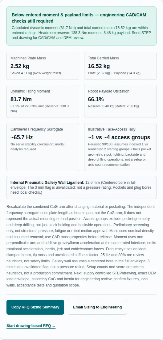
- Machined Plate Mass
- 2.52 kg
- Saved 4.11 kg (62% weight relief)
- Total Carried Mass
- 16.52 kg
- Plate (2.52 kg) + Payload (14.0 kg)
- Dynamic Tilting Moment
- 81.7 Nm
- 37.1% of 220 Nm limit (Reserve: 138.3 Nm)
- Robot Payload Utilization
- 66.1%
- Reserve: 8.48 kg (Rated: 25.0 kg)
- Cantilever Frequency Surrogate
- ~65.7 Hz
- No servo stability conclusion; modal analysis required
- Illustrative Face-Access Tally
- ~1 vs ~4 access groups
- Heuristic 90/100; assumes indexed 1 vs reoriented 2 starting groups. Omits pocket geometry, stock holding, backside and deep-drilling operations; not a setup or axis-count recommendation.
Recalculate the combined CoG arm after changing material or pocketing. The independent frequency surrogate uses plate length as beam span, not the CoG arm; it does not represent the actual mounting or load position. Access groups exclude pocket geometry and deep drilling, not just stock holding and backside operations. Preliminary screening only, not structural, pressure, fatigue or robot-motion approval. Mass uses nominal density and assumed removal; use CAD mass properties before release. Moment uses one perpendicular arm and additive gravity/linear acceleration at the same rated interface; omits rotational acceleration, inertia, jerk and cable/contact forces. Frequency uses an ideal clamped beam, tip mass and unvalidated stiffness factor; 25 Hz and 80% are review heuristics, not safety limits. Gallery wall assumes a centered bore in the full envelope; 3 mm is an unvalidated flag, not a pressure rating. Setup counts and score are access heuristics, not a production commitment. Next: supply controlled STEP/drawing, exact OEM load envelope, assembly CoG and inertia for engineering review; confirm fixtures, local walls, acceptance tests and quotation scope.
Published ; reviewed . Maintained by EOAT Machining. Next review: 2027-05-07.
Decide the chassis concept before committing to machining
Check the exact wrist limits
Interface dimensions do not establish payload, moment or inertia capacity.
Evidence and scope: ISO 9409-1:2004 — Robot mechanical interface plates
Treat removal as an assumption
Compare 36–68% what-if removal; confirm CAD mass and section stiffness independently.
Evidence and scope: NASA CR-124075 — Isogrid Design Handbook (1973)
Agree functional acceptance
Drawing datums and inspection scope establish the required part evidence.
Evidence and scope: ASME Y14.5-2018 (R2024) — Dimensioning and Tolerancing
1. Monolithic chassis or modular assembly?
Use a monolithic chassis when integral angled pads and fewer intermediate joints justify the billet and machining cost. Retain modular tooling when frequent finger repositioning or replaceable damage zones dominate. Wrist and actuator fasteners remain in both designs.
Concept comparison only. Fewer intermediate joints can simplify the load path; neither construction guarantees slip resistance or stiffness. Schematic illustration; not a fabrication print. Scroll the diagram on small screens.
| Decision | Monolithic plate | Modular assembly |
|---|---|---|
| Load path | Fewer intermediate joints; section stiffness still requires analysis | Joint preload and contact compliance require analysis |
| Serviceability | One damaged pad can require a complete replacement | Replace individual wedges or modules |
| Cost exposure | Billet removal, special reach and fixtures | Assembly labor, purchased hardware and maintenance |
| Environment | Pocket drainage and cleanability must be designed | Interfaces may need access for cleaning |
Evidence and scope: VDI 2230 Part 1:2015 — Joints with one cylindrical bolt
2. Moment, payload and inertia are separate checks
The tool estimates M = m × 9.80665 × (1 + aG) × L, with L in metres, using the combined carried mass and one perpendicular moment arm. This scalar gravity-plus-linear-acceleration case omits rotational acceleration, jerk, cable forces, contact forces and joint compliance. A lower mass alone does not establish a faster cycle.
The tool uses one perpendicular arm and additive gravity and linear acceleration. Actual vector moments and rotational inertia require OEM simulation. Schematic illustration; not a fabrication print. Scroll the diagram on small screens.
| Quantity | What is known here | What remains unknown |
|---|---|---|
| Mass | Envelope × nominal density × remaining fraction + tooling/part | Actual CAD volume and omitted accessories |
| Moment | Scalar moment at the entered reference | Pose-dependent vector load and axis-specific OEM limits |
| Inertia | Not calculated | Full CAD inertia tensor and OEM motion validation |
| Reference | Arm and limit must use the same interface | Extra offset and mass from a tool changer |
Evidence and scope: ISO 9409-1:2004 — Robot mechanical interface plates
3. Pocketing presets are sensitivity inputs
Compare mass assumptions before paying for detailed pocket design. The triangular-rib handbook is a structural reference, not evidence that this particular mounting plate retains a stated stiffness. For POM-C the tool caps removal at 50% and uses the 0.74 stiffness factor as an illustrative modelling choice; this is not a polymer design rule.
Removal percentages are calculator presets, not measured machining results. Rib stiffness cannot be inferred from removal percentage alone. Schematic illustration; not a fabrication print. Scroll the diagram on small screens.
| Preset | Assumed removal | Assumed stiffness factor | Release requirement |
|---|---|---|---|
| Solid | 0% | 1.00 relative reference | Actual section and supports |
| Perimeter | 36% | 0.82, unvalidated | CAD volume, skin and wall review |
| Orthogrid | 50% | 0.74, unvalidated | Rib geometry and load-path analysis |
| Isogrid | 62% | 0.68, unvalidated | CAD/FEA; no guaranteed stiffness retention |
| Sculpted undercut | 68% | 0.61, unvalidated | CAM reach, fixtures and structural analysis |
Evidence and scope: NASA CR-124075 — Isogrid Design Handbook (1973)
4. Emergency stops require the actual load case
An emergency stop is not represented by a universal acceleration or shock multiplier. Request the robot motion and stopping load envelope. Removing material changes both global bending stiffness and local rib stability; stronger alloy alone does not fix an unstable thin wall.
Both the complete section and individual ribs need verification. No universal shock multiplier, allowable stress or rib aspect ratio is supplied. Schematic illustration; not a fabrication print. Scroll the diagram on small screens.
| Risk | Missing evidence | Minimum follow-up |
|---|---|---|
| Global deflection | Actual supports and force directions | FEA with the assembled load path |
| Local buckling | Rib depth, width, imperfections and edge conditions | Local stability analysis |
| Fatigue | Cycle count, load spectrum and stress concentrations | Joint and section fatigue assessment |
| Collision | Contact stiffness and stopping distance | Application-specific protection and validation |
Evidence and scope: NASA CR-124075 — Isogrid Design Handbook (1973)
5. Specify functional datums before machining
A mounting face, pilot axis and clocking feature can form a useful reference frame. Choose tolerances from the actuator alignment stack-up. Five-axis access can reduce datum transfers, but stock holding and the underside often require another operation. No zero-error or universal Ø0.020 mm capability is implied.
The datum arrangement is illustrative. Define feature tolerances from the assembly stack-up and agree inspection access before quotation. Schematic illustration; not a fabrication print. Scroll the diagram on small screens.
| Drawing item | Buyer input | Acceptance question |
|---|---|---|
| Primary face | Flatness and mating condition | Is it inspected in free or restrained state? |
| Pilot and clocking | Fits, orientation and material condition | Are datums accessible after coating? |
| Angled pads | Position/profile and angle requirement | Which features control the tool centre point? |
| General tolerances | Explicit standard and edition | Are legacy ISO 2768-2 callouts intentional? |
Evidence and scope: ASME Y14.5-2018 (R2024) — Dimensioning and Tolerancing · ISO 22081:2021 — General geometrical and size specifications
6. Interface designation does not determine capacity
Obtain the exact robot or tool-changer drawing, including variants, screw engagement restrictions and locating features. ISO 9409-1 addresses interface geometry; a bolt-circle designation does not supply robot moment capacity or installation torque. This page therefore provides no generic flange moment or torque lookup.
Schematic interface only, not an ISO dimensional template. Use the exact robot or tool-changer drawing; obtain load limits separately. Schematic illustration; not a fabrication print. Scroll the diagram on small screens.
| Required datum | Source of truth | Do not infer from |
|---|---|---|
| Pilot, bolt and clocking geometry | Exact OEM interface drawing | A similar robot family |
| Payload and moment/inertia envelope | OEM load chart and motion evaluation | Bolt-circle diameter |
| Screw grade, engagement and torque | OEM installation instructions and joint calculation | Aluminum alloy name alone |
| Tool-changer contribution | Changer CAD, mass and limits | Bare-wrist rating |
Evidence and scope: ISO 9409-1:2004 — Robot mechanical interface plates
7. Internal galleries trade hose access for inspection work
The tool assumes a centered round bore: wall = (plate depth − bore diameter) / 2. Its 3 mm review flag is an unvalidated heuristic, not approval for 6–8 bar air or vacuum. Pockets, plug counterbores, threads and drill wander can reduce the true local ligament below this estimate. External tubing remains a practical alternative when access or testing is uncertain.
A centered cylindrical bore gives wall = (depth − diameter) / 2 before pockets and counterbores. This is not the minimum local wall or a pressure rating. Schematic illustration; not a fabrication print. Scroll the diagram on small screens.
Internal corners, drill drift, installation features and intersecting passages can govern leakage or breakout. Select the plug series and test plan per manufacturer guidance. Schematic illustration; not a fabrication print. Scroll the diagram on small screens.
| Check | Tool coverage | Required evidence |
|---|---|---|
| Centered bore wall | Envelope-only estimate | Minimum local CAD wall including pockets |
| Plug installation | Not calculated | Selected series, material, bore and wall instructions |
| Pressure/vacuum | Not calculated | Agreed pressure, leakage, cleanliness and test method |
| Serviceability | Not calculated | Blocked passage recovery or external routing option |
Evidence and scope: SFC KOENIG — Expander plug design guidelines
Need to resolve material, wall or wrist-load unknowns? Request a drawing-based DFM review with your STEP file, controlled drawing and load case.
8. Choose material by the governing failure mode
Displayed density and modulus are nominal reference inputs for sensitivity comparisons, not certified lot properties. Strength, temper, thickness, thermal range and chemical exposure need project-specific documentation. POM-C is a copolymer acetal; it should not be described as the Delrin homopolymer grade.
| Material | Nominal density (g/cm³) | Nominal E (GPa) | Decision limit |
|---|---|---|---|
| 6061-T6 | 2.70 | 68.9 | Obtain temper/thickness data and finish requirements |
| 7075-T651 | 2.81 | 71.7 | Higher strength does not imply a large stiffness gain |
| MIC-6 | 2.77 | 71.0 | Confirm stock data and final flatness after pocketing |
| 304 | 7.93 | 193 | Assess chemistry and increased carried mass |
| 316L | 8.00 | 193 | No universal cleaning or corrosion immunity |
| POM-C | 1.41 | 2.8 | Creep, temperature and lower stiffness may govern |
9. A cantilever surrogate is not modal approval
The displayed frequency uses I = b·t³/12, k = 3·E·factor·I/L³ and f = √(k/m)/(2π). It treats the complete envelope as an ideal clamped cantilever, with the carried mass at its tip and an unvalidated pocketing stiffness factor. Real mounting plates have different supports, mass distribution and joint compliance. Values are not clipped into an apparently realistic band.
The 25 Hz flag is an unvalidated review trigger. Above it, structural modes, damping, robot pose and excitation remain unknown. Schematic illustration; not a fabrication print. Scroll the diagram on small screens.
| Screening flag | Meaning | Next action |
|---|---|---|
| f < 25 Hz | Unvalidated low-frequency review trigger | Obtain assembly modal analysis or test |
| f ≥ 25 Hz | No conclusion about servo safety or settling | Compare measured modes, damping and excitation |
| Load utilization > 80% | Heuristic headroom review trigger | Check sensitivity to mass, CoG and OEM envelope |
| Any load utilization > 100% | Exceeds an entered limit in this scalar model | Revise concept or robot selection before release |
10. Check joints rather than applying a generic torque
Thread engagement, preload scatter and parent thread stripping depend on the joint. Inserts can improve repairability and wear resistance, but do not supply a universal percentage strength gain. For a nominal pin bearing example, F/(d·t) = 1000 N/(6 mm × 10 mm) = 16.7 MPa; this is average projected stress, not a design allowable or a dowel capacity rating.
Thread engagement and insert selection depend on load, alloy, lubrication and geometry. No universal tightening torque or strength gain is implied. Schematic illustration; not a fabrication print. Scroll the diagram on small screens.
Pin shear, hole bearing, edge distance and load sharing require separate checks; a standardized dowel is not a joint load approval. Schematic illustration; not a fabrication print. Scroll the diagram on small screens.
| Failure mode | Required input | Action |
|---|---|---|
| Thread stripping | Parent material, engagement, thread geometry | Joint-specific calculation |
| Loss of clamp | Preload, friction scatter, separation load | Specify tightening and verification method |
| Pin shear / parent bearing | Force sharing, pin diameter and engaged thickness | Check pin and parent material separately |
| Edge breakout | Ligament, geometry and load direction | No universal 1.5d or 2d safe distance |
Evidence and scope: VDI 2230 Part 1:2015 — Joints with one cylindrical bolt
11. Manage expansion without overconstraining locators
For an illustrative 300 mm span and 20 K change, using nominal αAl = 23.6 and αsteel = 12 µm/m·K gives differential travel (23.6 − 12) × 10⁻⁶ × 300 × 20 = 0.0696 mm. These assumed coefficients are not material certificates. A round locator and a relieved secondary locator can accommodate one direction when the remaining constraints allow it.
A relieved secondary locator can accommodate one expansion direction; verify travel, thermal range and remaining constraints. Schematic illustration; not a fabrication print. Scroll the diagram on small screens.
| Input | Illustrative value | Verify for release |
|---|---|---|
| Span / temperature change | 300 mm / 20 K | Actual thermal path and operating range |
| Coefficient mismatch | 11.6 µm/m·K assumed | Supplier material data over that range |
| Differential movement | 0.0696 mm calculated | Slot travel, tolerance and retained alignment |
12. Compare access before choosing simultaneous five-axis
Flat pockets and coplanar pads may need only three-axis milling; indexed 3+2 can address many angled faces. Simultaneous five-axis motion is justified by access and surface requirements, not by the search keyword. For the same ideal tool section and load, deflection varies with L³: increasing L/D from 3 to 7 gives (7/3)³ = 12.7× deflection, not a machining accuracy prediction.
For the same ideal cantilever tool and force, deflection varies with overhang cubed. The drawing is not a shop tolerance guarantee. Schematic illustration; not a fabrication print. Scroll the diagram on small screens.
| Geometry | Process to evaluate | Cost / feasibility question |
|---|---|---|
| Flat faces and pockets | 3-axis | Can standard tools reach without extra fixtures? |
| Several fixed-angle pads | Indexed 3+2 | Are critical features reachable in one datum setup? |
| Sculpted surfaces / undercuts | Simultaneous 5-axis or special tooling | Are tool, holder and rotary clearances sufficient? |
| Hidden backside features | Second operation likely | How will datum transfer be measured? |
Evidence and scope: ISO 10791-7:2020 — Accuracy of finished test pieces
13. Specify finishes and evidence as part of acceptance
Coatings change fits and electrical contact behavior. Put mask areas, finished dimensions, cosmetic needs and verification methods on the drawing. A machine cutting test or CMM performance certificate does not certify the delivered plate. Agree material records, treatment records and feature reports in the quotation; they are not promised for every order by this page.
Illustrative coating build and penetration. Verify treatment thickness, dimensional allowances and mask areas with the finisher; the drawing implies no universal growth ratio. Schematic illustration; not a fabrication print. Scroll the diagram on small screens.
Machine performance tests, in-process probing and part acceptance serve different purposes. Agree the delivered inspection record for this drawing. Schematic illustration; not a fabrication print. Scroll the diagram on small screens.
| Acceptance item | Specify | Evidence to request |
|---|---|---|
| Pilot / dowel fits | After-treatment size and mask plan | Measured features in final condition |
| Electrical bond | Contact area and assembled resistance criterion | Agreed assembled continuity test |
| Gallery sealing | Medium, differential pressure and leak limit | Part-specific test record |
| Critical GD&T | Datums, features, uncertainty and sampling | Agreed part inspection report |
Evidence and scope: ISO 10360-2:2009 — CMM acceptance and reverification tests · ISO 10791-7:2020 — Accuracy of finished test pieces
14. Reproducible worked scenarios
Illustrative calculations, not customer projects or measured field outcomes. Unlisted selections and values use the visible baseline. Each result uses the same model as the tool; keep the entered robot limits unchanged when evaluating an overload.
Baseline aluminum chassis
Overrides: none. Baseline: 320 × 240 × 32 mm, 6061-T6, 62% selected removal preset, dual 15° pads, Ø8 mm dual gallery, 14 kg tooling/part, 180 mm arm, 1.8 G, 220 Nm and 25 kg limits. POM-C caps removal at 50%; applied removal and stiffness factor are printed below.
Plate 2.52 kg · carried 16.52 kg · moment 81.7 Nm · applied removal 62% · unvalidated stiffness factor 0.68 · cantilever surrogate 65.7 Hz · centered-bore wall 12.0 mm · status: ok (screening only).
Next: Confirm actual CAD mass, combined CoG and OEM motion envelope.
Long-overhang heavy tooling
Overrides: payloadMass=50; overhangCg=450; robotAcceleration=3. Baseline: 320 × 240 × 32 mm, 6061-T6, 62% selected removal preset, dual 15° pads, Ø8 mm dual gallery, 14 kg tooling/part, 180 mm arm, 1.8 G, 220 Nm and 25 kg limits. POM-C caps removal at 50%; applied removal and stiffness factor are printed below.
Plate 2.52 kg · carried 52.52 kg · moment 927.1 Nm · applied removal 62% · unvalidated stiffness factor 0.68 · cantilever surrogate 36.8 Hz · centered-bore wall 12.0 mm · status: overload (screening only).
Next: Exceeds an entered limit: revise the concept or robot selection before release; do not change a rating just to obtain a passing result.
Thin gallery envelope
Overrides: thickness=13. Baseline: 320 × 240 × 32 mm, 6061-T6, 62% selected removal preset, dual 15° pads, Ø8 mm dual gallery, 14 kg tooling/part, 180 mm arm, 1.8 G, 220 Nm and 25 kg limits. POM-C caps removal at 50%; applied removal and stiffness factor are printed below.
Plate 1.02 kg · carried 15.02 kg · moment 74.3 Nm · applied removal 62% · unvalidated stiffness factor 0.68 · cantilever surrogate 17.8 Hz · centered-bore wall 2.5 mm · status: warning (screening only).
Next: Review the 2.5 mm centered-bore wall flag; inspect minimum local ligaments and plug installation requirements.
Stainless mass sensitivity
Overrides: material=316l-ss. Baseline: 320 × 240 × 32 mm, 6061-T6, 62% selected removal preset, dual 15° pads, Ø8 mm dual gallery, 14 kg tooling/part, 180 mm arm, 1.8 G, 220 Nm and 25 kg limits. POM-C caps removal at 50%; applied removal and stiffness factor are printed below.
Plate 7.47 kg · carried 21.47 kg · moment 106.1 Nm · applied removal 62% · unvalidated stiffness factor 0.68 · cantilever surrogate 96.4 Hz · centered-bore wall 12.0 mm · status: warning (screening only).
Next: Confirm chemistry and surface requirements and re-evaluate the wrist envelope with actual CAD mass.
Polymer stiffness sensitivity
Overrides: material=pom-c; length=1000; thickness=12. Baseline: 320 × 240 × 32 mm, 6061-T6, 62% selected removal preset, dual 15° pads, Ø8 mm dual gallery, 14 kg tooling/part, 180 mm arm, 1.8 G, 220 Nm and 25 kg limits. POM-C caps removal at 50%; applied removal and stiffness factor are printed below.
Plate 2.03 kg · carried 16.03 kg · moment 79.2 Nm · applied removal 50% · unvalidated stiffness factor 0.74 · cantilever surrogate 0.6 Hz · centered-bore wall 2.0 mm · status: warning (screening only).
Next: Review the low cantilever surrogate frequency, creep and thermal effects; no servo-safe conclusion is available.
Reproduce the baseline calculator result
Actual software run captured on 2026-11-07. Reset the calculator to reproduce: 320 × 240 × 32 mm, 6061-T6, 62% assumed removal, dual 15° pads, Ø8 mm dual gallery, 14 kg attached tooling and part, 180 mm common arm, 1.8 G additional acceleration, and entered limits of 220 Nm and 25 kg. Estimated plate mass is 2.52 kg, total carried mass 16.52 kg and scalar moment 81.7 Nm.
15. Frequently asked sourcing and engineering questions
1. Process and datums
What makes this a mounting plate rather than an adapter plate?
It is the tooling chassis carrying multiple actuators, sensors or vacuum zones. A wrist adapter primarily connects interfaces. One part can perform both roles; specify the load path and all mounting faces.
Does every mounting plate require five-axis machining?
No. Flat and coplanar features can suit three-axis milling. Evaluate indexed 3+2 for fixed angled pads and simultaneous five-axis only when tool access or surface geometry requires it.
Can the complete part always be made in one setup?
No. Workholding, underside access, stock removal and inspection access can require additional operations. The displayed setup comparison is an illustrative access heuristic, not a quotation.
What tolerance can be quoted for angled actuator pads?
Supply functional datum and position/profile requirements. Feasibility and cost depend on part size, tool reach, material, fixture plan and final treatment; confirm them in a drawing-based quote.
How should general tolerances be called out?
Name the standard and edition explicitly. ISO 22081 replaces ISO 2768-2; do not silently convert a legacy drawing or treat general tolerances as a substitute for critical interface callouts.
2. Load and structural screening
Does an ISO 9409-1 designation specify moment capacity?
No. It identifies interface geometry. Obtain payload, moment and inertia limits from the exact robot or tool-changer documentation.
What mass is included in the tool output?
Assumed remaining plate mass plus the entered tooling and part mass. Include grippers, fasteners, valves, sensors, changer, cables and all accessories in the appropriate input or CAD evaluation.
How is dynamic moment calculated?
The tool uses total mass × 9.80665 × (1 + entered acceleration in G) × perpendicular lever arm in metres. This is one scalar load case, not robot motion simulation.
What does a result below the entered limits establish?
Only that this assumed scalar moment and estimated mass are below the numbers entered. It does not approve stiffness, fatigue, inertia, stopping loads or OEM motion performance.
Is the 25 Hz frequency flag a servo safety threshold?
No. It is an unvalidated review trigger on an ideal cantilever surrogate. Real modal frequencies, damping and excitation require assembly analysis or testing at relevant robot poses.
3. Lightweighting and material
Are 50%, 62% and 68% removal measured outcomes?
No. They are what-if volume-removal presets. Replace them with CAD mass properties before release; they do not guarantee retained stiffness or shorter cycles.
Can stronger 7075 replace a stiffness analysis?
No. Strength and elastic stiffness are different properties. The nominal elastic moduli used here are similar; section geometry and supports strongly influence deflection.
Why is polymer removal capped at 50%?
This is an illustrative model cap, not a certified POM-C design rule. Creep, temperature, section stiffness and service loads still need a separate assessment.
Does MIC-6 guarantee flatness after pocketing?
No finished-part flatness is guaranteed by this tool. Confirm stock condition, machining sequence, restraint and inspection requirements with the supplier.
Does 316L automatically qualify food or cleanroom tooling?
No. Geometry, drainage, surface condition, chemistry, temperature, particle generation and application acceptance all matter. Confirm requirements for the complete assembly.
4. Joints, galleries and finish
What torque should be used for the flange screws?
Use the exact OEM installation instructions and verify the actual joint, fastener grade, engagement and friction conditions. This page supplies no generic torque approval.
Do inserts guarantee a fixed pull-out strength improvement?
No. Insert length, parent material, preparation, installation and failure mode determine the result. Select and verify the insert for the actual joint.
What does the displayed gallery wall mean?
It is half of plate depth minus bore diameter, assuming a centered bore in an unpocketed envelope. It can overestimate the actual minimum local wall and does not rate pressure or vacuum service.
Are expander plugs automatically leak-free in this plate?
No. Select a series and follow its material, bore, wall and installation requirements. Agree and perform the complete-part leakage and pressure or vacuum test.
How should anodize and electrical contacts be specified?
Define final fits, treatment, mask boundaries and assembled contact requirements on the drawing. Verify the finished assembly instead of assuming a universal dielectric or resistance value.
5. Procurement and handoff
What should be sent for a useful RFQ?
Send STEP and a controlled 2D drawing, material and temper, robot interface drawing, load/CoG information, quantity, finish, critical acceptance features and required date.
What if the calculator inputs are unavailable?
Copy the incomplete parameters or use the inquiry form or email. Mark unknown values explicitly and request a drawing-based review rather than substituting the baseline as approved data.
What is the production lead time?
Timing depends on drawing maturity, stock, treatment, inspection scope, quantity and capacity. Request a confirmed schedule in the quotation; this page does not promise a fixed turnaround.
Which inspection documents are included?
Agree the required material, finish, dimensional and leakage records before ordering. This page does not claim every batch automatically includes every certificate.
How should confidential drawings be shared?
Confirm the NDA and approved transfer channel with the supplier before sharing restricted files. The inquiry form starts that conversation; confidential document handling is subject to the agreed process.
16. Drawing-based RFQ and release checklist
Copy the screening summary, then provide STEP plus a controlled 2D drawing; material/temper; exact wrist or changer interface; load cases and combined CoG; quantity; finish and mask plan; critical datums; required inspection and leakage records; and your requested date. Unknown values should remain marked as unknown. Confirm the NDA and transfer channel before sending confidential drawings.
RFQ review establishes process feasibility, evidence and delivery scope. Manufacturing setup count and ship date are confirmed in the quotation. Schematic illustration; not a fabrication print. Scroll the diagram on small screens.