
5-axis calculator + sourcing guide
5-Axis Machined End Effector Adapter Plate
Estimate mass and bending moment, compare machining routes, and prepare a drawing review. Reviewed .
Request DFM & quote5-Axis EOAT Adapter Plate Mass & Dynamics Screener
Estimate adapter mass and transverse bending moment. Relief percentages are assumptions; confirm mass and the 3D load case from CAD.
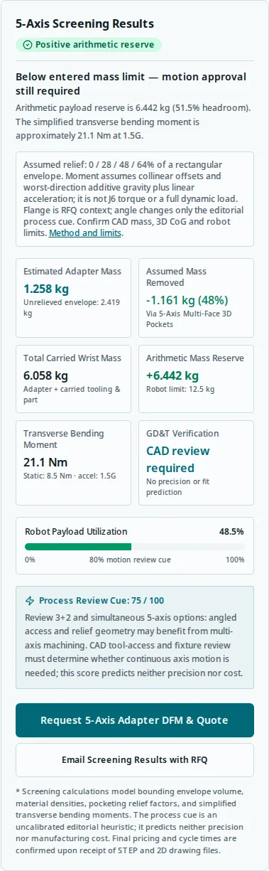
5-Axis Screening Results
Positive arithmetic reserveArithmetic payload reserve is 6.442 kg (51.5% headroom). The simplified transverse bending moment is approximately 21.1 Nm at 1.5G.
Assumed relief: 0 / 28 / 48 / 64% of a rectangular envelope. Moment assumes collinear offsets and worst-direction additive gravity plus linear acceleration; it is not J6 torque or a full dynamic load. Flange is RFQ context; angle changes only the editorial process cue. Confirm CAD mass, 3D CoG and robot limits. Method and limits.
- Estimated Adapter Mass
- 1.258 kg
- Unrelieved envelope: 2.419 kg
- Assumed Mass Removed
- -1.161 kg (48%)
- Via 5-Axis Multi-Face 3D Pockets
- Total Carried Wrist Mass
- 6.058 kg
- Adapter + carried tooling & part
- Arithmetic Mass Reserve
- +6.442 kg
- Robot limit: 12.5 kg
- Transverse Bending Moment
- 21.1 Nm
- Static: 8.5 Nm · accel: 1.5G
- GD&T Verification
- CAD review required
- No precision or fit prediction
Review 3+2 and simultaneous 5-axis options: angled access and relief geometry may benefit from multi-axis machining. CAD tool-access and fixture review must determine whether continuous axis motion is needed; this score predicts neither precision nor cost.
* Screening calculations model bounding envelope volume, material densities, pocketing relief factors, and simplified transverse bending moments. The process cue is an uncalibrated editorial heuristic; it predicts neither precision nor manufacturing cost. Final pricing and cycle times are confirmed upon receipt of STEP and 2D drawing files.
By EOAT Machining. First recorded .
Key decisions before releasing a drawing
Use geometry to choose the process
Compare 3-axis fixtures, indexed 3+2 access and simultaneous motion using CAM and a datum plan. A machine axis count does not guarantee precision.
Details: Use geometry to choose the processTreat relief as an assumption
The 0 / 28 / 48 / 64% presets compare estimated mass only. No stiffness or fatigue retention is calculated.
Details: Treat relief as an assumptionVerify the complete robot load
Positive arithmetic reserve still needs model-specific CoG, inertia and trajectory validation.
Details: Verify the complete robot loadOrder evidence with the part
Agree finished-feature inspection, material traceability and circuit tests before quoting.
Details: Order evidence with the partBest suited to integrators comparing angled or pocketed EOAT interfaces before CAD review. For a simple flat plate, start with a 3-axis quote; for a load-critical design, use the screen only to prepare the engineering inputs.
3-axis, 3+2 or simultaneous 5-axis?
The following is a process-planning comparison, not measured cycle time or capability data. Quote the same geometry, tolerances, batch and inspection scope to compare cost fairly. Review our CNC machining capabilities when preparing the process requirements.
| Route | Useful geometry | Main trade-off | Evidence needed |
|---|---|---|---|
| 3-axis | Flat faces and accessible holes; angled fixtures can extend access | Fixture transfers versus simpler programming | Fixture plan and datum inspection |
| 3+2 indexed | Discrete angled faces and drilling directions | Access without continuous rotary motion | Index positions, tool reach and clamping-face operation |
| Simultaneous 5-axis | Surfaces requiring changing tool orientation | CAM, collision checks and kinematic calibration | Toolpath simulation and finished-feature inspection |
| Metal additive + finishing | Channels or topology inaccessible to cutters | Post-machining, powder removal and process qualification | Leak, material and dimensional qualification |
Screening method and explicit assumptions
Dimensions are in mm, density in g/cm³, masses in kg, and g = 9.80665 m/s². The unrelieved baseline is a rectangular envelope; flange circularity, holes and chamfers are not inferred.
Mass estimate
m0 = L × W × T × density / 1,000,000
m_adapter = m0 × (1 − f_relief)
Reserve = entered robot mass limit − adapter − carried tool and part. Relief is a selected assumption, never a CAD-derived prediction.
Transverse bending estimate
M0 = g × [m_adapter × T/2 + m_tool × (T + d)] / 1000
M_screen = M0 × (1 + G)
Collinear offsets are assumed perpendicular to the load, with gravity and transverse acceleration adding. Compound angle is not projected into a 3D load vector. This is not J6 drive torque.
| Item | What the tool does | Required follow-up |
|---|---|---|
| Flange designation | Stored in RFQ context only; no effect on arithmetic | Manufacturer interface drawing and full assembly fit check |
| Relief style | Applies 0 / 28 / 48 / 64% assumed removal | CAD mass properties, bosses and load paths |
| Angle and thickness | Angle affects only the editorial process cue; thickness also sets assumed arms and volume | 3D CoG and collision/tool-access review |
| Process cue | 20 baseline; angle +30 (>0°) or +45 (≥45°); deep pockets +25 or isogrid +35; thickness ≥40 mm +10; capped at 100 | Uncalibrated editorial heuristic; ≥65 review multi-axis, ≥40 review indexing; no accuracy or price prediction |
| 80% usage marker | Editorial prompt for closer load review | All usage levels require the model-specific load check |
| Precision, fatigue and compliance | Not calculated | Drawing, FEA where needed, and measured finished-part evidence |
Input limits are software bounds, not manufacturing capacity or validated safe ranges. Results update synchronously. Missing or out-of-range inputs suppress numeric results; reset or send partial inputs for review.
Flange interface and fastening release checks
ISO 9409-1:2004 defines circular interface dimensions, designation and marking. It does not assign load-carrying ranges. Obtain the exact robot revision drawing and installation manual; a matching pitch circle alone does not establish interchangeability.
| Check | Required input | Release action |
|---|---|---|
| Pilot and clocking | Robot pilot form, diameter, fit, dowel location and coating allowance | Verify concentric fit and angular orientation in assembly |
| Fastener preload | Robot limits, bolt grade, lubrication/friction and joint stack | Calculate joint preload and use approved installation torque |
| Thread engagement | Parent material, insert type, preload and available blind depth | Check stripping, pull-out and bolt bottoming |
| Plate envelope | Fastener heads, edge margins and adjacent ribs or passages | Check clearances and bearing stresses in CAD |
Material selection: strength is not stiffness
Supplier nominal densities support mass screening; product form, temper, thickness and procurement specification control allowable properties. The tool calculates no strength, stiffness, fatigue or corrosion margin. At equal geometry, switching from 6061 to 7075 increases mass.
Use the EOAT material selection guide to compare the broader material shortlist before specifying alloy, product form and finish.
| Material | Screen density (g/cm³) | Reason to investigate | Limitation / evidence |
|---|---|---|---|
| 6061-T6 aluminum | 2.70 | General machined EOAT concept | Kaiser nominal density; confirm product-form properties |
| 7075-T651 aluminum | 2.80 | Strength-driven design after structural review | Kaiser sheet/plate data; confirm temper, corrosion and fatigue |
| 17-4 PH, H1150 | 7.82 | Strength and wear requirements with specified aging | Carpenter H1150 data; verify cleaning chemistry and heat treatment |
| Ti-6Al-4V Grade 5 | 4.43 | Application-specific material or compatibility need | Fine Tubes nominal density; qualify actual billet and finish |
For aggressive washdown, compare 316L or other compatible alloys against the actual chemistry. Neither stainless material choice nor internal routing alone proves hygienic or cleanroom compliance.
Weight relief without assuming retained rigidity
NASA CR-124075, Isogrid Design Handbook (1973) concerns triangular integral stiffened structures. Applying that concept to a finite EOAT plate requires its own interface, stress, buckling and vibration assessment. It supplies no universal 64% mass reduction or retained-stiffness claim for this adapter.
| Concept | Assumed removal | Mass retained | Unverified design question |
|---|---|---|---|
| Solid envelope | 0% | 100% | Which stock actually remains after machining the perimeter? |
| 2.5D pockets | 28% | 72% | Are the mounting bosses, floor and drilling walls adequate? |
| Deep multi-face pockets | 48% | 52% | Can tools reach the pockets without excessive deflection? |
| Triangular / isogrid concept | 64% | 36% | Do local stress, buckling and modal checks justify the webs? |
Compound angles: check tool and cell access
An angled interface may improve access around a machine door, but changes the tool frame and mass distribution. Check the entire trajectory, services, fixtures and emergency-stop motion. A collision-free sketch is not a validated robot cell.
Internal porting: design for flow, cleaning and testing
Internal cross-drilled passages can reduce exposed tubing, while introducing intersections, trapped debris and plug interfaces. Confirm drill access, deburring, wall margins and cleanability. Specify service and test conditions before selecting closures.
| Decision | Known requirement to record | Verification |
|---|---|---|
| Flow and evacuation | Cup/chamber volume, pressure targets, pump and valve curves, cycle target | Test the complete circuit through its operating pressure range |
| Drilled passages | Bore path, intersections, ligament thickness and cleanability | Access review, deburring verification and cleanliness inspection |
| Expansion plug | Exact part number, base material and pressure direction | Use the selected SFC KOENIG series drawing, not family maxima |
| Leak/proof test | Medium, pressure, stabilization time, temperature and allowable leakage | Agree test method and record results; positive-pressure rating alone does not prove vacuum sealing |
Why diameter alone cannot predict evacuation time
Pfeiffer’s laminar conductance model is C = pi × d^4 × p_mean / (128 × viscosity × L), with SI units. At equal length, viscosity and mean pressure, an 8 mm bore has 16 times the ideal laminar conductance of a 4 mm bore. That ratio does not predict pump-limited evacuation time, leakage, valve restrictions or other flow regimes.
Mass reserve, bending moment and robot approval
Universal Robots’ UR10e payload guidance requires consideration of payload mass, CoG and inertia and describes acceleration adjustment. Apply the manual for the actual robot model and revision; a flange designation is not a payload rating.
Mass reserve
Rated mass minus estimated total mass. Positive reserve alone cannot approve a trajectory.
Transverse bending
M = F × perpendicular lever arm. The screen uses a simplified additive gravity and linear-acceleration scenario.
Axis-specific inertia
I_axis = I_CoG + m r_perp². Use perpendicular distance to the chosen axis; axial offset is not the J6 radial lever arm.
Next step at every result state: export CAD mass properties for the complete adapter, tool, workpiece and services; check the manufacturer load model and trajectory, including emergency deceleration. The calculator does not predict acceleration improvement or cycle time.
Datum-based GD&T and inspection planning
ASME Y14.5-2018 (R2024) provides a drawing language, not a machine capability guarantee. Use mating face A, centering pilot B and clocking feature C where function supports that scheme; choose the feature controls and values from assembly requirements.
A shared setup can reduce transfer error, but clamping distortion, rotary calibration, temperature and cutter deflection remain. No fixed position tolerance is inferred from this screen. ISO 2768-1:1989 addresses general dimensional tolerances; ISO 2768-2:1989 is withdrawn and replaced by ISO 22081:2021. Resolve editions and legacy callouts with the customer instead of silently substituting limits.
Four reproducible screening examples
Illustrative calculations, not customer projects or validated production results. Every example uses a 160 × 160 × 35 mm envelope, 4.8 kg carried tool/part, 140 mm tool-face-to-CoG distance, 1.5 G transverse acceleration and 12.5 kg entered mass limit. Flange selection does not alter the arithmetic.
| Assumed concept | Density (g/cm³) | Relief | Adapter mass | Total mass | Reserve | Bending moment |
|---|---|---|---|---|---|---|
| 6061 solid baseline | 2.70 | 0% | 2.419 | 7.219 | 5.281 | 21.6 |
| 6061 deep-pocket assumption | 2.70 | 48% | 1.258 | 6.058 | 6.442 | 21.1 |
| 7075, same deep-pocket geometry | 2.80 | 48% | 1.305 | 6.105 | 6.395 | 21.2 |
| 7075 isogrid assumption | 2.80 | 64% | 0.903 | 5.703 | 6.797 | 21.0 |
Interpretation: equal-geometry 7075 is heavier than 6061. More assumed relief lowers computed mass and moment, while structural adequacy remains unknown. Reproduce an example using the material and relief selectors, then replace the estimate with CAD data before acting.
Specify the evidence required with delivery
ISO 10360-2:2009 covers acceptance and reverification of CMM performance. It does not assign this job a machine accuracy or a part tolerance. Agree the measurement plan, uncertainty and acceptance rule for the actual features. Review the quality documentation requirements alongside the controlled drawing.
| Requirement | Record to request | Acceptance basis |
|---|---|---|
| Flange and tool datums | Dimensional report with feature IDs, datums, measured values and method | Approved drawing and agreed measurement decision rule |
| Material and temper | Traceable mill/heat-treatment certificates | Ordered alloy, product form and condition; chemistry alone cannot verify temper |
| Coating and fit | Finish certificate, masked features and post-finish fit checks | Drawing coating specification, thickness and mating fits |
| Internal circuit | Pressure or vacuum test log and cleanliness record | Agreed test medium, pressure, dwell, temperature and leakage limit |
Risks, cost drivers and practical alternatives
| Risk | Consequence | Mitigation / alternative |
|---|---|---|
| Treating a mass estimate as approval | Overload, deflection or dynamic faults | Use CAD and robot load analysis; reduce tooling mass or shorten offsets |
| Aggressive thin-web relief | Chatter, distortion, local buckling or vibration | Review tool reach and FEA; retain thicker bosses or simpler pockets |
| Unnecessary simultaneous machining | Programming and qualification cost without useful benefit | Quote 3-axis or indexed 3+2 on the same drawing |
| Asymmetric material removal | Warp after unclamping | Review stock temper, balanced roughing and finish sequence |
| Finish alters fits or threads | Assembly interference or poor retention | Agree masking and finish allowance; inspect after coating |
| Internal routing mismatches service | Trapped contamination or inaccessible leaks | Review cleanability; use removable passages or accessible tubing where appropriate |
Public evidence is insufficient for a universal cost multiplier, lead time, cycle-time saving or precision advantage. Request a quote with programming, fixtures, material, machining, finishing and inspection separated where useful.
Primary sources and evidence boundaries
Checked October 26, 2026. Sources below support the stated scope; public abstracts do not replace controlled standards or manufacturer installation drawings. Relief presets, the process cue and worked examples are explicitly editorial assumptions and calculations.
- ISO 9409-1:2004: interface scope, designation and marking; no load-carrying correlation.
- ASME Y14.5-2018 (R2024): GD&T language and drawing interpretation.
- ISO 2768-1:1989 and withdrawn ISO 2768-2:1989: general tolerancing scope and edition status.
- ISO 10360-2:2009: CMM performance verification; no claimed job-specific accuracy.
- Kaiser 6061 nominal density and Kaiser 7075 sheet/plate data: screening densities; allowable properties depend on product and condition.
- Carpenter Custom 630 / 17-4 PH data and Fine Tubes Grade 5 data: density inputs, with actual billet properties to confirm.
- NASA CR-124075 (1973): isogrid design background; no EOAT retained-stiffness or machining ratio guarantee.
- SFC KOENIG sealing families: select the exact series and request its installation specification; family pressure maxima are not design approval.
- Pfeiffer vacuum fundamentals, conductance: flow-regime and mean-pressure dependence of pipe conductance.
- Universal Robots UR10e maximum payload: model-specific mass, CoG and inertia guidance; not a universal robot envelope.
Send a reviewable RFQ package
- STEP model and controlled 2D PDF: robot model, interface drawing, datum scheme, fits and functional tolerances.
- Material, temper, surface treatment, masking, inserts, quantity and drawing revision.
- Complete tool and workpiece mass, 3D CoG, inertia, motion/load cases and installation requirements.
- Internal passage medium, operating conditions, cleanliness and agreed leak/proof-test acceptance.
Confirm NDA and file-handling requirements before sharing controlled drawings. Review our IP protection and drawing handoff process with the RFQ contact.
Request adapter DFM & quoteInquiry Email
Attach your CAD files (STEP, IGES) and tolerances for quick quoting.
Related: 316 adapter plates · 316 vacuum manifolds · Tool changer adapters.
Engineering and sourcing questions
Process selection
When does an adapter plate benefit from 5-axis machining?
Consider multi-axis access for angled mounting faces, difficult pockets or port directions. Flat plates can often use 3-axis machining. Compare actual tool reach, fixtures and datums; an angled face alone does not require simultaneous 5-axis motion.
How does 3+2 differ from simultaneous 5-axis?
3+2 indexes the part or tool to a fixed orientation before cutting. Simultaneous machining changes orientation while cutting. Use the latter when surface geometry or collision avoidance needs continuous motion; confirm this in CAM.
Can a single setup machine both sides?
Only if workholding and tool clearance expose the required features. A clamping face or sacrificial stock may require a second operation. Quote the operation plan rather than assuming zero refixturing.
Could additive manufacturing be an alternative?
Consider it for inaccessible internal passages or topology that cannot be milled. Compare post-machining of datums, powder removal, leak qualification and inspection with a billet design. Cost, fatigue life and vacuum integrity need project evidence.
Flange fit and fastening
Does ISO 9409-1 define robot payload or tightening torque?
No. It specifies interface dimensions, designation and marking, without assigning load-carrying ranges. Obtain payload limits and installation requirements from the exact robot model manual.
Does choosing a flange in the calculator verify fit?
No. The designation is RFQ context only. Check the manufacturer drawing for pilot dimensions, hole clocking, thread depth, dowel fit, edge distance and interference in the full CAD assembly.
How should dowel fits be chosen?
Separate the retained pin end from the removable mating end. Specify both hole and pin tolerances, coating allowance and assembly temperature on the drawing; fit class names alone do not establish retention or guaranteed repeatability.
How do I specify fastener torque and engagement?
Use the robot manufacturer installation limits and a joint calculation covering bolt grade, friction, preload, tapped material, insert data and blind-hole depth. No universal torque or engagement table applies to every aluminum adapter.
Material and weight decisions
Is 7075 lighter than 6061?
At equal geometry it is slightly heavier: this screen uses 2.80 versus 2.70 g/cm³ from supplier data. Its strength may allow a geometry change, but stiffness, fatigue and buckling must be checked before thinning a wall.
Is 17-4 PH a default choice for washdown?
No. Specify heat treatment and assess the actual cleaning chemistry, temperature, exposure and hygienic geometry. Compare 316L or other suitable materials when corrosion or cleaning requirements dominate.
Are the 28%, 48% and 64% relief values measured capability?
No. They are illustrative mass-removal assumptions for comparing concepts. Actual removal depends on bolt bosses, load paths, port walls, tool access and workholding. Replace the estimate with CAD mass properties before release.
Does an isogrid guarantee retained stiffness?
No. NASA describes triangular integral stiffened structures, but finite EOAT plates have local interfaces and out-of-plane loads. Compare deflection, stress, buckling and natural frequencies for the actual load cases.
Loads and internal channels
What does the displayed moment mean?
It is a simplified transverse bending moment using collinear lever arms and gravity plus transverse linear acceleration in the same direction. It is not J6 drive torque and excludes angular acceleration, 3D mass distribution and the robot trajectory.
Does positive payload reserve approve robot operation?
No. Reserve is entered mass limit minus estimated total mass. Validate the complete gripper, part, adapter and services using CAD mass, 3D CoG, inertia and the manufacturer load model, including emergency stops.
Does doubling a vacuum bore cut evacuation time by sixteen?
Not in general. At equal mean pressure, viscosity and length, ideal laminar pipe conductance scales with diameter to the fourth power. Pump speed, valves, leaks, chamber volume and flow regime determine actual evacuation time. Test the complete circuit.
Which expander plug bore specification should I use?
Select the exact plug series and part number, then use its manufacturer drawing for bore diameter, roundness, roughness, edge distance and pressure direction. Do not transfer a family maximum pressure or one series tolerance to another.
Inspection and procurement
Does single-setup machining guarantee a position tolerance?
No. It can reduce transfer error, but machine kinematics, tool deflection, clamping, thermal drift and inspection uncertainty remain. Agree feature-level tolerances and demonstrate them on the finished part.
Can I use ISO 2768-mK on a new drawing?
Resolve the drawing standard and edition with the customer. ISO 2768-2:1989, associated with the K geometric class, is withdrawn and replaced by ISO 22081:2021. This is not an automatic substitution of numeric limits. Keep legacy requirements explicit.
What should the inspection package contain?
Agree the material certificate, datum-based dimensional report, coating and fit checks, and any leak or proof test before quoting. Define sampling, measurement uncertainty, test pressure, temperature, dwell and acceptable leakage.
What is needed for a manufacturability review?
Send STEP and a controlled 2D PDF with robot model and interface drawing, datums, fits, load cases, material and temper, coating, quantity and required tests. Email the screening assumptions as context; drawing approval still controls production.