
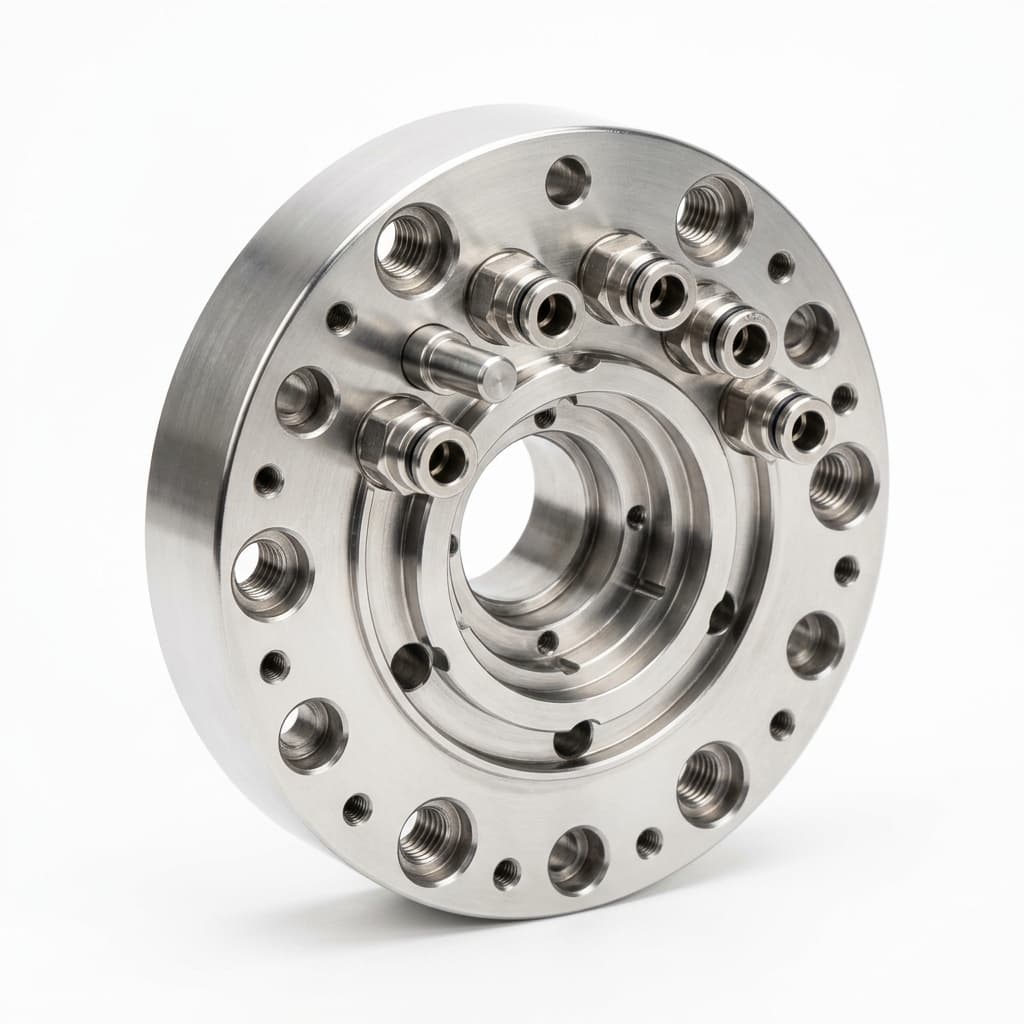
Robotic Automatic Tool Changers (ATC): Machining Tolerances and Procurement Specs for EOAT
Specify robotic Automatic Tool Changers for EOAT machining: repeatability, fail-safe locks, utility ports, payload moments, and supplier QA checks.
When automating a high-mix, low-volume production line, swapping end-of-arm tooling (EOAT) manually is no longer a viable option. Robotic Automatic Tool Changers (ATCs)—also known as robotic quick-change tooling (QCT)—allow a single robot arm to switch between a vacuum gripper, a CNC deburring spindle, and a 2-jaw parallel gripper within seconds.
However, an ATC introduces a mechanical break in the robot’s kinematic chain. If the two halves of the tool changer (the Master side on the robot arm, and the Tool side on the EOAT) do not couple with absolute rigidity, the robot loses its repeatability.
TL;DR (Executive Summary): The performance of an Automatic Tool Changer is dictated by the CNC machining tolerances of its locking mechanism and locating datums. Published ATC data shows repeatability as tight as 0.0006 in (0.0152 mm), but cycle life and payload limits are model-specific and must be checked under your acceleration, moment, and utility-port loads. For procurement teams, choosing between a premium ATC (like ATI or Stäubli) and a budget alternative requires evaluating the machining precision of the locking taper, the surface finish of the pneumatic seals, and the rigidity of the master/tool interface.
This guide bridges the gap between ATC data sheets and the CNC machining precision required to achieve them. It is designed for procurement teams, distributors, and automation engineers who need to source, specify, and evaluate reliable automatic tool changers for their robot cells.
Scope note (published and reviewed July 23, 2026): This article focuses on machined ATC master/tool plates, adapter plates, locating datums, and utility interfaces for global industrial and collaborative robot cells. It is not a replacement for a robot risk assessment, supplier-specific load derating, ISO 9409-1 flange verification, or validation under your actual acceleration, contamination, cable, fluid, and maintenance conditions.
RFQ shortcut: If your team is evaluating an ATC package, send the master/tool CAD, robot model, flange pattern, payload and moment envelope, utility ports, target repeatability, and inspection requirements through Contact / RFQ. For adjacent procurement inputs, align the request with the tool-changer adapter plate capability, materials guide, quality documentation expectations, and compliance documentation page.
1. The Mechanics of Repeatability: Why CNC Machining Matters
When a robot moves to a coordinate (e.g., X: 150.00, Y: 200.00, Z: 50.00), the robot controller assumes a fixed Tool Center Point (TCP). If the ATC allows even a microscopic amount of play (slop) between the robot wrist and the end effector, the actual TCP will drift. In precision machining, inserting a dowel pin, or placing a semiconductor wafer, a 0.1 mm drift can cause catastrophic crashes.
The Role of Locating Pins and Reamed Holes
Repeatability in an ATC is achieved through kinematic coupling—usually a combination of precision-machined locating dowel pins and corresponding reamed holes or V-grooves.
- The Master Side (Robot): Typically features hardened steel locating pins pressed into tightly toleranced bored holes.
- The Tool Side (EOAT): Features corresponding receptacles.
To achieve a standard ATC repeatability of ±0.03 mm, the CNC machining of these locating features must be held to a much tighter tolerance—often ±0.005 mm (H7/g6 fits). If a supplier uses standard drilling instead of precision boring and reaming, the ATC will exhibit "wobble" under high moment loads.
Locking Mechanisms: Zero-Freeplay vs. Traditional Ball-Lock
The locking mechanism pulls the Tool plate into the Master plate and holds it there, resisting the immense moment of inertia generated when a robot arm decelerates abruptly.
Cross-Section: ATC Zero-Freeplay Cam Locking Mechanism
- Traditional Ball-Lock: Uses a simple pneumatic piston to push steel balls into a groove on the tool ring. While cheap to manufacture, the balls sit in a static pocket. Under extreme moment loads, the master and tool can momentarily separate, causing micro-impacts that wear down the aluminum body over time.
- Zero-Freeplay Cam-Lock: Uses a precision-machined, multi-angled cam profile. As pneumatic pressure is applied, the cam continuously drives the locking balls outward and upward against a tapered tool ring. Because the cam angle is machined to a specific geometry (often a self-locking angle to prevent dropping the tool if air pressure is lost), it automatically compensates for microscopic wear over millions of cycles, ensuring the plates remain rigidly coupled with absolute zero freeplay.
2. Structural Specs: ATC Procurement Comparison
When comparing ATCs from premium brands (like ATI or Stäubli) versus generic alternatives, procurement teams must look past the maximum payload number. The true indicator of quality lies in the moment capacity, the surface treatments, and the fail-safe mechanisms.
| Specification | Entry-Level/Generic ATC | Industrial/Premium ATC (e.g., ATI QC Series) | Why It Matters for Engineering & Procurement |
|---|---|---|---|
| Machining Tolerance | ±0.05 mm (General Milling) | ±0.005 mm (Precision Boring & Grinding) | Dictates the TCP repeatability. Low tolerance causes assembly wobble and premature wear. |
| Locking Mechanism | Simple Ball-Lock in Aluminum | Zero-Freeplay Cam in Hardened Rc58 Steel | Prevents the EOAT from shifting under high acceleration or emergency stops. |
| Fail-Safe Operation | Relies solely on continuous air pressure | Mechanical self-locking spring/cam profile | Crucial: A fail-safe ATC will not drop the heavy EOAT if the factory loses compressed air. |
| Surface Finish (Body) | Standard Anodizing (Type II) | Hard-Coat Anodized AL7075 (Type III) | Prevents galling, scratching, and corrosion when deployed in harsh CNC machining environments. |
| Pass-Through Sealing | Standard Buna-N O-rings | Precision face seals with micro-machined glands | Ensures vacuum and pneumatic lines do not leak across the Master/Tool interface. |
| Cycle Life | Often unpublished, or stated without rated-load test conditions | Model-specific published endurance testing; request the rated-load test protocol | Determines total cost of ownership (TCO) and maintenance downtime frequency. |
3. Utility Pass-Throughs: Pneumatic, Vacuum, and Electrical
An ATC does not just physically hold the tool; it must seamlessly pass utilities (air, power, data) from the robot arm to the EOAT. The reliability of these pass-throughs is entirely dependent on the CNC machining of the interface plates.
Pneumatic and Vacuum Integrity
Many EOATs utilize suction cups or pneumatic cylinders. The master and tool plates feature internal cross-drilled channels and face seals to pass air.
- Machining Defect Risk: If the O-ring glands (the grooves that hold the rubber seals) are machined with poor surface finish (e.g., chatter marks from a worn end-mill), the compressed air or vacuum will slowly leak.
- Vacuum vs. Pressure: Vacuum is notoriously harder to seal than positive pressure. If your EOAT relies on high-flow vacuum generators, specify an ATC where the pneumatic ports are machined with a surface roughness of Ra 0.8 or better.
Electrical Pin Blocks
Smart EOATs (using IO-Link, vision cameras, or servo grippers) require electrical pass-throughs. The electrical contact blocks use spring-loaded pogo pins. If the master and tool plates are not machined perfectly parallel, the tool plate will couple at a slight angle. Over time, this uneven mating will permanently compress the pins on one side of the electrical block, leading to intermittent data loss or power failure when the robot moves rapidly.
4. Material Selection and Heat Treatment
Procurement teams should verify the materials used in the construction of the ATC.
- The Body: Typically machined from high-strength aerospace aluminum (AL7075-T6 or AL6061-T6) to keep the weight low, maximizing the robot's available payload.
- The Locking Components (Cams, Pins, Receptacles): Must NEVER be bare aluminum. These high-stress contact points should be machined from tool steel (such as 4140 or A2) and heat-treated to 50-60 HRC. Some advanced ATCs use stainless steel 430F or 316L for washdown and food-grade environments.
If a supplier quotes an abnormally light ATC, verify that they haven't substituted heavy steel locking components with anodized aluminum to cut costs. Aluminum-on-aluminum locking mechanisms will gall, seize, and fail rapidly.
5. Heavy-Duty vs. Cobot Payload Considerations
The rise of collaborative robots (cobots) has shifted ATC design.
- Cobot ATCs (e.g., for FANUC CRX or Universal Robots): These are optimized for low weight and low profile to keep the center of gravity close to the robot wrist. They often feature manual or semi-automatic push-button releases and handle payloads from 5 kg to 20 kg. Machining here focuses on thin-wall aluminum optimization.
- Heavy-Duty ATCs (Foundry, Spot Welding, Palletizing): Designed for payloads exceeding 100 kg to 1,000 kg. These ATCs face massive static and dynamic moments. The CNC machining of the master plate often includes large mounting flanges tailored specifically to the ISO 9409-1 bolt patterns of heavy industrial robots.
6. Procurement Checklist: Evaluating ATC Suppliers
When soliciting quotes or selecting an OEM for automatic tool changers, use this engineering checklist to vet the supplier's technical capability:
- Repeatability Specification: Does the supplier document repeatability under load (e.g., ±0.015 mm) and the test condition used?
- Locking Mechanism Type: Is it a Zero-Freeplay cam design, or a static ball-lock?
- Fail-Safe Verification: Will the locking mechanism mechanically hold the tool if the pneumatic air supply drops to 0 psi?
- Material Certification: Are the locking pins and receptacles made of hardened steel (Rc 50+)?
- Moment Capacity Validation: Does the datasheet list static and dynamic moment limits (Nm), not just a flat payload weight?
- Electrical Compatibility: Does the ATC support standard industrial protocols (EtherNet/IP, PROFINET, IO-Link) with shielded pin blocks?
- Utility Port Sizing: Are the pneumatic ports threaded adequately (e.g., G1/8 or G1/4) to supply the required CFM for your vacuum generators?
7. The Hidden Costs of Low-Tolerance ATCs
A common mistake in EOAT procurement is buying a $500 generic ATC for a $40,000 robot cell, only to suffer from thousands of dollars in hidden costs.
- Downtime from Crashes: If the ATC allows 0.2 mm of slop, a CNC machine tending robot will eventually crash the billet into the chuck jaws, breaking tooling and halting production.
- Maintenance Frequency: Low-tolerance ATCs wear out faster, requiring the maintenance team to constantly replace O-rings, re-grease locking cams, or replace the entire unit every 6 months.
- Data Loss: Poor coupling leads to intermittent IO-Link sensor dropouts, causing the PLC to throw phantom errors that take hours to diagnose.
Investing in a high-precision, CNC machined ATC upfront reduces the risk that the mechanical coupling becomes the weakest link in your automation cell.
8. Frequently Asked Questions (FAQ)
Q: Do I need a robotic tool changer if my robot only performs one task? A: If the EOAT is never changed during its lifecycle, an ATC is an unnecessary expense. Hard-mounting the EOAT directly to the robot flange using a precision machined adapter plate is safer, lighter, and cheaper. ATCs are exclusively for high-mix environments where the robot must change tools dynamically.
Q: What is the difference between a manual tool changer and an automatic one? A: Manual tool changers use a hand-actuated lever to lock and unlock the plates. They are excellent for fast manual changeovers between shifts. Automatic tool changers (ATCs) are actuated via pneumatic pressure controlled by the robot's PLC, allowing the robot to change tools completely unattended during a production cycle.
Q: How does an ATC handle loss of air pressure? A: High-quality ATCs incorporate a "Fail-Safe" mechanism. A powerful internal spring pushes the locking cam into the locked position. Air pressure is only required to unlock the ATC. If the plant loses air, the spring holds the heavy EOAT safely, preventing it from crashing to the floor.
Q: Can I pass fluid (coolant or water) through an ATC? A: Yes. Many suppliers offer fluid pass-through modules. However, these require highly specialized, self-sealing valves machined into the plates to ensure coolant doesn't spray when the tool is disconnected.
9. Sources & References
For further validation of ATC specifications, repeatability ranges, and fail-safe mechanics, refer to the following industry sources:
- ATI Industrial Automation: QC-29 Tool Changer flyer with published 0.0006 in repeatability and utility-module specifications. ATI QC-29 Tool Changer flyer
- Plastics Machinery & Manufacturing: Industry coverage of ATI's QC-29 downsized robotic tool changer, including repeatability, fail-safe locking, and service-module context. ATI downsizes robotic tool changer
- FANUC America: CRX-ready ATI end-effectors listing that highlights ISO flange compatibility and fail-safe pneumatic locking for cobot applications. ATI CRX-Ready End-Effectors
At EOAT Machining, we understand that every micron matters. Whether you are integrating a high-end ATC or need custom, lightweight adapter plates and manifolds to connect your robot to your tooling, our CNC machining services deliver uncompromising precision. We specialize in holding H7 tolerances for dowel pins, cutting zero-leak O-ring glands, and delivering production-ready aluminum and steel components.
Contact our engineering team today to discuss the machining requirements for your next End-of-Arm Tooling project.
Author

Categories
More Posts
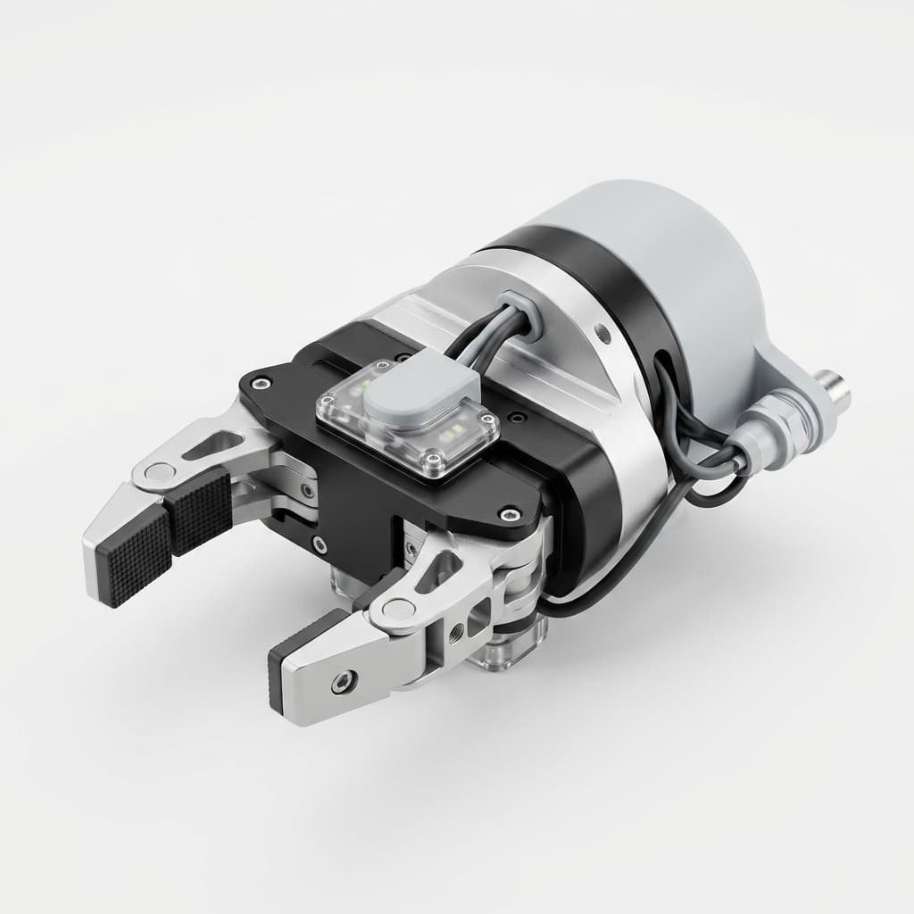
Custom CNC Machining for AI Vision-Guided EOAT: Calibration Stability and Procurement Guide
Prevent hand-eye calibration drift in vision-guided EOAT with CNC machined camera mounts, DFM rules, tolerance notes, and an RFQ checklist.
Cleanroom & ESD-Safe EOAT Machining: ISO 14644-1 Procurement Guide
Procurement guide to specify cleanroom and ESD-safe EOAT machining for ISO 14644-1 cells: compare finishes, risks, QA checks, and request DFM support.
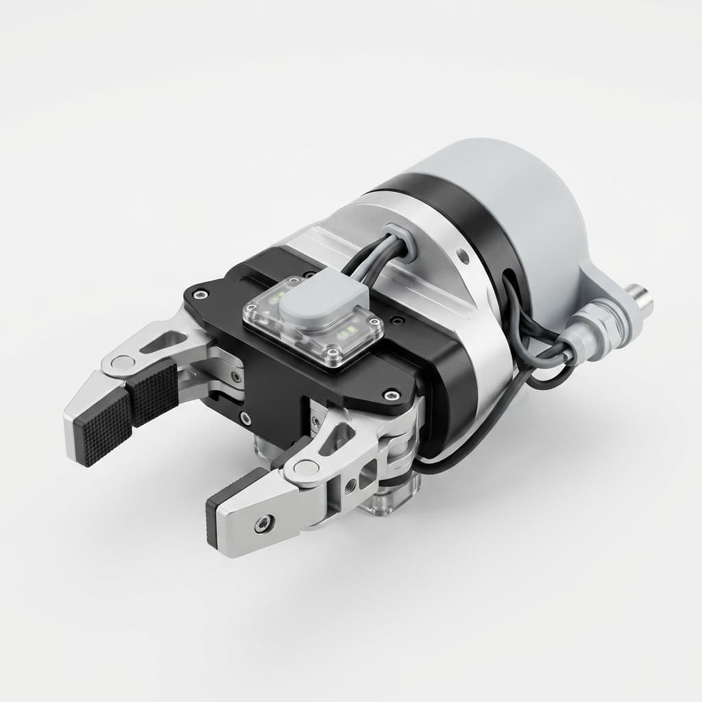
How ISO 10218:2025 Updates Change EOAT Safety and Compliance in Machining
Discover how the new ISO 10218-1:2025 and ISO 10218-2:2025 standards merge collaborative robot safety into a unified framework, and what it means for end-of-arm tooling in CNC machining.