
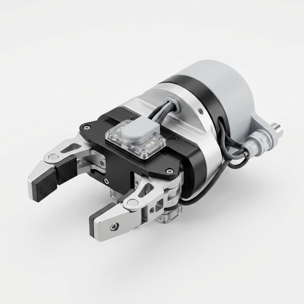
Machining Smart EOAT: Designing for IO-Link and Sensor Integration
An engineering guide to designing and CNC machining custom end-of-arm tooling that natively integrates sensors, vision systems, and IO-Link architecture.
For global EOAT machining programs in 2026, industrial automation is shifting from passive mechanical grippers to intelligent, data-generating nodes. As machine tending, high-mix assembly, and precision packaging demand real-time feedback, integrating IO-Link sensors, vision systems, and force-torque monitors into End-of-Arm Tooling (EOAT) is no longer optional—it is a baseline requirement.
However, a critical bottleneck has emerged: the mechanical hardware gap. While software protocols and sensor form factors have advanced rapidly, the physical aluminum and steel bodies of custom EOAT are often still designed as if they were passive tools. Automation engineers and procurement teams frequently find themselves retrofitting delicate electronics onto rigid machined bodies using zip-ties, external brackets, and exposed wiring.
This approach leads to catastrophic failure modes on the production floor. Cables snag on safety fencing, coolant pools around exposed inductive sensors, and collisions crush protruding vision cameras. To build truly resilient smart EOAT, the sensor integration must be natively designed into the CNC machined body from the very first CAD iteration.
This guide provides a comprehensive framework for mechanical engineers and procurement teams to design, specify, and source custom CNC machined EOAT bodies that protect, route, and optimize modern smart sensor networks.
TL;DR (Executive Summary): Slapping sensors onto an existing gripper body is a recipe for downtime. Smart EOAT requires purpose-built CNC machining strategies: deeply pocketed sensor housings, internally milled cable routing, glare-reducing surface finishes, and strict GD&T controls to maintain sensor focal lengths under dynamic loads.
Scope and review date: Published July 19, 2026 for automation engineers, controls teams, and procurement buyers specifying CNC machined EOAT for global robot cells. The guidance applies to custom aluminum, stainless steel, and engineering-plastic end effectors that carry discrete sensors, IO-Link devices, compact cameras, vacuum switches, RFID heads, or force/torque sensors. It is not a substitute for the sensor OEM installation manual, robot cell safety risk assessment, or final electrical design review; confirm cable bend radius, IP rating, connector orientation, datum scheme, and inspection plan with the controls engineer and CNC supplier before release.
1. The Cost of Afterthought Sensor Integration
Before detailing how to properly machine a smart EOAT body, it is essential to understand why retrofitting fails. When an automation integrator buys a standard mechanical gripper or machines a basic custom adapter plate, adding sensors later introduces several points of failure:
- Cable Fatigue and Snagging: The number one cause of EOAT downtime is cable failure. Exposed cables routed outside the tool body are subject to high-speed whipping, bending fatigue, and snagging on peripheral cell equipment.
- Collision Vulnerability: A $1,500 CMOS vision sensor bolted to the exterior of a gripper flange becomes the furthest protruding point. In the event of a robot teaching error or coordinate drift, the sensor absorbs the impact rather than the robust aluminum structure.
- Coolant and Swarf Ingress: In CNC machine tending applications, the EOAT is frequently exposed to high-pressure coolant and metal chips. Sensors mounted on flat external surfaces without drainage pathways quickly suffer from liquid ingress or false readings caused by metal swarf accumulation over the sensor face.
Natively machining the sensor housings directly into the custom EOAT structure eliminates these failure modes. The goal is a "monolithic" design where the electronics are embedded securely within the protective envelope of the machined metal.
2. Core Machining Strategies for Sensor Integration
Deep Pocketing and Counterboring
Sensors should never be the highest point of contact on an end effector. The CNC machining process must be utilized to create recessed pockets for all sensitive electronics.
- Flush Mounting: Inductive proximity sensors and photoelectric sensors should be counterbored so their sensing faces sit flush with, or slightly sub-flush to, the gripper surface. This requires precise depth control (often ±0.05mm) during the milling process to ensure the sensor's range is not occluded by the surrounding metal.
- Collision Guards: If a sensor must protrude (such as an angled vision camera), the CNC program should leave a surrounding "lip" or machine a localized guard structure out of the solid billet. This ensures that any accidental impact is transferred into the aluminum chassis rather than the camera lens.
Sensor Integration: Retrofit vs. Native Machining
Internal Cable Routing: Gun Drilling and Milled Channels
IO-Link architecture dramatically reduces the sheer volume of cables, converting complex analog harnesses into single, standard, unshielded 3-wire or 4-wire cables. However, these cables still need protection.
- Milled Cable Channels with Cover Plates: The most serviceable approach is to use a 3-axis CNC mill to cut deep, serpentine channels along the non-structural faces of the EOAT body. Once the IO-Link cables are laid into these channels, a thin sheet metal or 3D printed cover plate is bolted over the top, securing and hiding the wires.
- Deep Hole Drilling (Gun Drilling): For highly robust environments (like heavy forging or die-casting EOAT), long internal bores can be drilled completely through the solid aluminum arms. This provides ultimate protection but makes initial wiring and subsequent sensor replacement more time-consuming.
Drainage and Swarf Management
When a sensor is recessed into a pocket, that pocket can inadvertently become a cup that holds fluids.
- Weep Holes: Every sensor pocket must be machined with a weep hole (e.g., a 3mm through-hole) drilled at the lowest gravitational point to allow CNC coolant, washdown water, or hydraulic fluid to escape.
- Chamfered Reliefs: To prevent metal chips (swarf) from packing around inductive sensors, machine wide chamfers or angled reliefs around the sensor face to encourage chips to fall away naturally during robot motion.
3. GD&T Requirements for Precision Sensing
Sensing is only as accurate as its mechanical mounting. A vision camera assessing part orientation with sub-millimeter accuracy is useless if its mounting bracket flexes or shifts due to thermal expansion. The application of Geometric Dimensioning and Tolerancing (GD&T) must bridge the gap between the mechanical datum structure and the sensor's optical or inductive requirements.
Table: Sensor Type vs. Machining Tolerance Requirements
When submitting custom EOAT drawings to a CNC machine shop, it is crucial to apply the right functional tolerances to the sensor mounting features. Over-tolerancing drives up costs, while under-tolerancing leads to erratic data.
| Sensor Category | Typical EOAT Application | Critical Machining Feature | Recommended GD&T / Tolerance Focus | Design Consequence if Failed |
|---|---|---|---|---|
| Inductive Proximity | Jaw open/close confirmation, part presence | Counterbore depth (Z-axis offset) | Profile of a Surface / Depth: ±0.1mm to maintain exact air gap. | Sensor crashes into part, or fails to trigger due to being too far back. |
| Force/Torque (F/T) | Deburring, grinding, precise assembly | Flange mating surface | Flatness: < 0.02mm over the mating diameter. | Warped mounting introduces mechanical pre-load, skewing force data and ruining calibration. |
| Vision Camera / 3D Profiler | Part recognition, bin picking, quality inspection | Camera mounting dowel holes and bracket angle | Perpendicularity & True Position: ±0.05mm true position to the tool center point (TCP). | Coordinate system drifts; robot picks air or crashes. Software compensation becomes unstable. |
| Laser Distance Measurement | Stack height monitoring, precise approaching | Alignment bore / threaded port | Angularity: < 0.5 degrees relative to the primary datum. | Laser spot misses the target entirely over a distance of 300mm+. |
| Vacuum Pressure Switch | Suction grip confirmation, predictive leak warning | Threaded pneumatic port (G1/8 or M5) | Thread Quality: Machined directly into billet, no galling. | Micro-leaks cause false pressure drops, triggering false alarms in the IO-Link diagnostic system. |
| RFID R/W Heads | Tool identification, pallet tracking | Non-metallic isolation pockets | Clearance: Maintaining minimum specified distance from surrounding steel. | Surrounding metal causes interference, reducing read range or blocking the signal entirely. |
4. Material Selection and Surface Finishes
The choice of material and its surface treatment directly impacts sensor performance.
- Avoiding Inductive Interference: Inductive proximity sensors detect the presence of metal. If you machine a tight pocket in steel for an unshielded inductive sensor, the surrounding steel body will trigger the sensor constantly. In these cases, the pocket must be oversized, or an aluminum body must be used if the sensor is calibrated for ferrous target detection only. Alternatively, Delrin (Acetal) inserts can be machined to isolate the sensor from the metallic EOAT body.
- Vision System Finishes: Bare machined aluminum is highly reflective. In machine tending applications, overhead factory lighting or integrated ring lights will bounce off bare aluminum chamfers and blind the vision camera. Any EOAT body mounting a vision system should be specified for Type II Matte Black Anodizing or a black oxide finish (for steel) to absorb stray light and increase visual contrast.
- Thermal Stability for High-Precision Sensors: For ultra-precise applications (e.g., semiconductor wafer handling), the coefficient of thermal expansion (CTE) becomes relevant. An aluminum arm holding a laser sensor may expand enough under factory temperature shifts to alter the focal point. In such extreme cases, CNC machining the EOAT from Invar or Titanium might be required to lock the sensor geometry in place.
5. Engineering & Procurement Checklist for Smart EOAT
For procurement teams and automation engineers qualifying CNC suppliers for smart EOAT manufacturing, use this checklist before finalizing the purchase order:
- Are all sensor datums defined? Ensure the drawing clearly links the sensor mounting pockets back to the primary robot flange datum (ISO 9409-1).
- Is internal cable routing accounted for? Verify that milled channels or drilled passages are present in the CAD, and that minimum cable bend radii are respected (usually 4x to 10x the cable diameter).
- Have weep holes been detailed? If the tooling will see fluids, ensure drainage holes are present and dimensioned.
- Is the surface finish specified for vision? If cameras are used, confirm the RFQ specifies matte, non-reflective finishes.
- Are flatnesses specified for F/T sensors? Confirm that the mating faces for any force/torque sensors have strict flatness callouts to prevent mechanical stress during bolt torquing.
- Can the supplier handle multi-axis setups? Internal routing often requires 4-axis or 5-axis machining to reach awkward angles without excessive manual setups. Ensure the machine shop has this capability.
RFQ note: If your drawing set already includes sensor datums, cable routing assumptions, and environmental exposure notes, send the CAD package through the contact form and ask for a DFM review focused on protected sensor pockets, routable cable channels, and inspectable datum features.
6. Frequently Asked Questions (FAQ)
Q: Does pocketing sensors into the aluminum body weaken the structural integrity of the gripper? A: It can, if poorly designed. However, finite element analysis (FEA) usually shows that the maximum stress occurs at the robot flange neck or the jaw pivot points. Placing sensor pockets in the thicker web sections of the aluminum billet rarely compromises overall strength. CNC lightweighting techniques actually rely on pocketing to reduce inertia.
Q: Can we use 3D printing to create internal cable channels instead of CNC machining? A: Yes. Additive manufacturing (like FDM or SLS) is excellent for creating complex internal, winding cable channels. However, as noted in our CNC Machining vs. 3D Printing comparison, printed parts may lack the structural rigidity, cyclic fatigue strength, and precision tolerances required for heavy-duty machining EOAT. A hybrid approach—CNC machining the structural frame and 3D printing the cable guide covers—is often the optimal solution.
Q: Why use IO-Link instead of traditional discrete wiring for EOAT? A: IO-Link reduces a massive bundle of analog wires down to a standard 3-wire or 4-wire digital cable. For an EOAT with 8 distinct sensors, this means passing one small cable back through the robot's slip ring instead of 24 individual wires. It also allows for predictive diagnostics (e.g., a sensor reporting that its lens is getting dirty before it completely fails).
Q: How do I handle pneumatic lines alongside sensor cables? A: Best practice in custom CNC machined EOAT is to keep them separated. Machine internal pneumatic manifolds with cross-drilled channels directly through the solid metal, and use shallow surface-milled channels to route the electrical cables. This prevents an air leak from pressurizing a cable channel and blowing off the cover plate.
7. Conclusion: Engineering the Backbone of Smart Automation
Integrating intelligence into End-of-Arm Tooling is fundamentally a mechanical engineering challenge. The most advanced IO-Link architecture and AI-driven vision algorithms will fail if the physical mounting shifts by a millimeter, or if a cable is sheared off during a routine cycle.
By treating sensor integration as a core requirement during the CAD phase, and leveraging advanced CNC machining techniques—deep pocketing, internal routing, and rigorous GD&T—manufacturers can create smart EOAT that survives the harsh realities of the production floor.
Sources and References for Further Reading
- IO-Link Community: IO-Link Technology
- ISO: ISO 9409-1:2004 Manipulating industrial robots - Mechanical interfaces - Plates
- ATI Industrial Automation: Force/Torque Documentation and Manuals
At EOAT Machining, we don't just cut metal; we build the mechanical foundations for smart factories. If you are struggling to integrate complex sensor arrays, vision systems, or IO-Link architectures into your custom robot tooling, you need a manufacturing partner who understands both precision CNC machining and automation realities.
Contact our engineering team today to submit your CAD files for a comprehensive Design for Manufacturability (DFM) review and quotation on your next smart EOAT project.
Author

Categories
More Posts
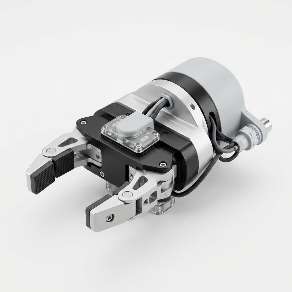
Custom CNC Machining for AI Vision-Guided EOAT: Calibration Stability and Procurement Guide
Prevent hand-eye calibration drift in vision-guided EOAT with CNC machined camera mounts, DFM rules, tolerance notes, and an RFQ checklist.
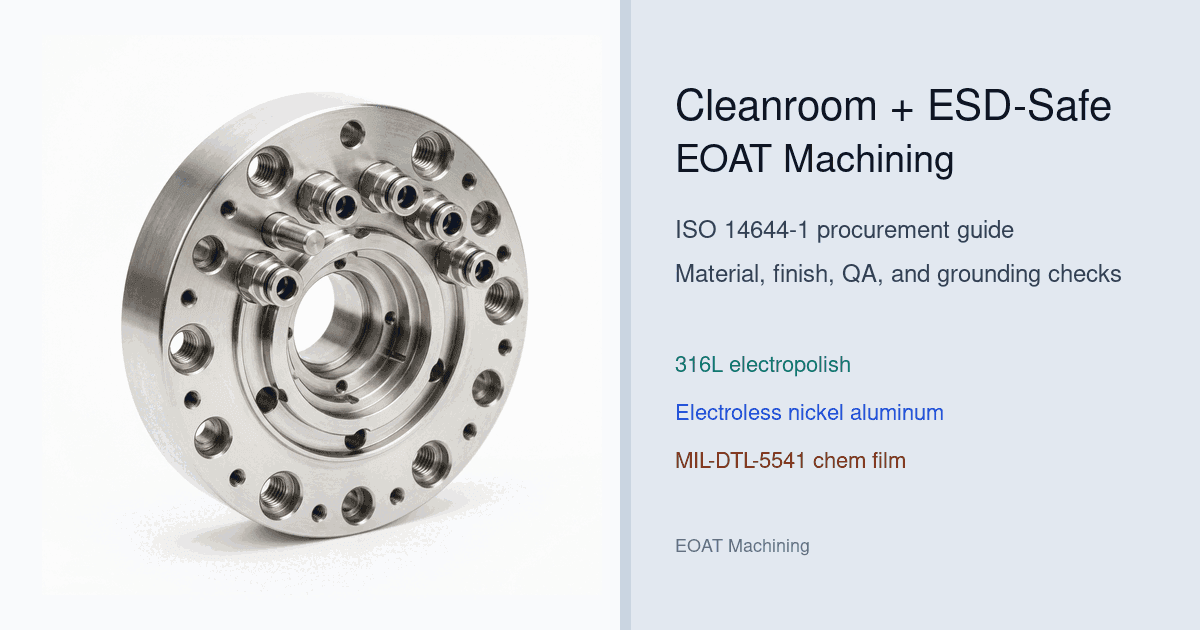
Cleanroom & ESD-Safe EOAT Machining: ISO 14644-1 Procurement Guide
Procurement guide to specify cleanroom and ESD-safe EOAT machining for ISO 14644-1 cells: compare finishes, risks, QA checks, and request DFM support.
EOAT Machining Tolerances and Surface Finishes: A Buyer's Guide
Use this EOAT machining buyer's guide to set practical tolerances, surface finishes, ISO 2768 notes, and RFQ checks before quoting custom tooling.