
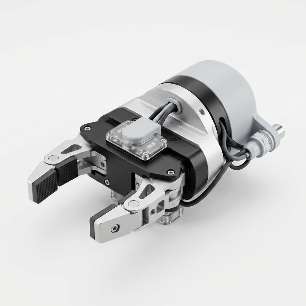
Custom CNC Machining for AI Vision-Guided EOAT: Calibration Stability and Procurement Guide
Prevent hand-eye calibration drift in vision-guided EOAT with CNC machined camera mounts, DFM rules, tolerance notes, and an RFQ checklist.
For EOAT machining projects, integrating an AI-driven 3D vision system into a robotic cell—often referred to as an "eye-in-hand" configuration—is one of the most effective ways to enable dynamic bin picking, high-precision assembly, and real-time quality inspection. However, even the most advanced vision systems and AI models are physically bound by the mechanical integrity of the End-of-Arm Tooling (EOAT) that holds them.
A brilliant CAD model of an AI-vision guided EOAT means nothing if the physical assembly allows the camera to shift by 0.2 millimeters after a weekend of heavy production.
TL;DR (Executive Summary): To prevent hand-eye calibration drift in vision-guided robots, buyers and engineers must avoid flimsy extruded aluminum profiles and 3D printed camera brackets. Instead, invest in custom CNC machined monolithic mounts. You must: (1) Use H7 reamed dowel pins for repeatable mounting. (2) Keep the camera's Center of Gravity (CoG) as close to the robot's ISO 9409-1 wrist flange as possible. (3) Utilize AL7075-T6 for stiffness-to-weight optimization. (4) Design pockets for vibration damping elastomers to protect the sensor. (5) Avoid modular sliding joints that can creep over time.
This guide provides actionable Design for Manufacturing (DFM) rules, procurement strategies, and strict mechanical baselines for sourcing custom CNC machined EOATs tailored for AI vision systems.
Scope, date, and limits: Published July 25, 2026 for global procurement, automation engineering, and machine-builder teams specifying custom CNC machined EOAT for vision-guided robot cells. The recommendations focus on mechanical stability, RFQ clarity, and machinable design details; they do not replace robot OEM payload validation, machine safety risk assessment, or onsite hand-eye calibration acceptance testing.
1. The High Cost of Hand-Eye Calibration Drift
Before diving into CNC machining rules, procurement teams and integrators must understand the operational pain point: Calibration Drift.
What is Hand-Eye Calibration?
In an eye-in-hand setup, the camera is mounted directly on the robot's wrist (or on the EOAT itself). The vision system captures a point cloud or 2D image, and the AI determines where the target object is located in the camera's coordinate system. To pick the object, the robot controller must translate those coordinates into the robot's base coordinate system. The mathematical matrix that links these two spaces is generated during the Hand-Eye Calibration process.
As shown in Zivid's hand-eye calibration workflow for a UR robot, the calibration process depends on a repeatable relationship between captured vision data and robot poses. In production, that relationship only remains useful if the physical camera-to-tool geometry stays fixed.
The Mechanics of Drift
"Drift" occurs when that physical relationship changes. If a robotic arm decelerates aggressively at 2,000 mm/s, a poorly designed camera mount will vibrate, bend, or permanently slip.
- A shift of just 0.1 degrees at the mounting bracket creates about 1.7 mm of lateral error at a 1 m working distance, enough to miss a bin-picking edge, scrape a fixture, or drop a part.
- When drift occurs, the production line must be halted. An engineer must jog the robot through a calibration grid, capture new images, and recalculate the matrix—a process that costs thousands of dollars in unplanned downtime.
To eliminate drift, the physical mount must be treated as a precision aerospace component, not a glorified tripod.
2. Why Modular and 3D Printed Mounts Fail in Production
When prototyping, it is tempting to use 3D printed brackets (FDM or SLA) or modular aluminum extrusion kits (like 80/20 profiles) to mount a 3D camera like a Zivid Two or Mech-Mind sensor.
The Material Creep of Plastics
While 3D printing is excellent for lightweighting and complex geometries, standard thermoplastics (PLA, ABS, PETG) suffer from material creep under continuous load and thermal cycling. A camera that operates at 45°C (113°F) will slowly deform the plastic bracket holding it, silently corrupting the calibration matrix over a few weeks.
The Flex of Modular Extrusions
Modular aluminum extrusions rely on T-nuts and friction to hold position. In high-vibration environments—such as CNC machine tending or stamping press tending—these friction joints inevitably walk. A sudden emergency stop (E-Stop) can apply immense torque to a cantilevered camera, instantly knocking it out of alignment.
As noted in Zivid's mechanical considerations for robot-mounted cameras, avoiding unstable mounting, unmanaged vibration, and poor cable handling is the first step to a successful vision deployment.
3. CNC Machining Rules for Camera Rigid Mounting
To achieve zero-drift stability, you must transition to custom CNC machined aluminum or steel. Here are the specific DFM rules to enforce when designing and sourcing your vision EOAT.
Rule A: Monolithic vs. Assembled Designs
Every bolted joint in an assembly is a potential point of failure. The ideal vision EOAT is a monolithic structure—a single block of aerospace-grade aluminum machined to hold both the gripping mechanisms (suction cups, pneumatic parallel grippers) and the camera housing.
If a monolithic design is too complex or expensive to machine out of a single billet, the assembly must be mechanically locked, not just friction-clamped.
Rule B: H7 Dowel Pins are Mandatory
Never rely on the clearance of an M5 or M6 screw to locate a camera bracket. Screws provide clamping force, but they allow radial play.
- The Engineering Fix: Use press-fit or slip-fit dowel pin holes between critical mating surfaces.
- Specify H7 tolerance reamed holes (e.g., Ø5mm H7) on the drawing.
- This helps the camera return to a controlled mechanical location after maintenance, reducing the chance that the hand-eye calibration matrix needs a reteach.
DFM Visual: Camera Mounting Rigidity & Center of Gravity
Rule C: Thread Depth and Locking Mechanisms
A heavy 3D camera (often weighing 1-2 kg) will exert significant pull-out force on threads during rapid robot movements.
- Tapped holes in aluminum should have a thread depth of at least 2x to 2.5x the hole diameter to prevent stripping.
- Always specify chemical thread lockers (like Loctite 242) or mechanical lock washers on the assembly prints.
4. Managing Center of Gravity (CoG) and Moment of Inertia
Robots, particularly Collaborative Robots (Cobots), are highly sensitive to payload distribution. Industrial robot specifications, such as FANUC's LR Mate 200iD/14L page, treat payload and wrist inertia as selection constraints, so a poorly positioned camera can reduce allowable speed or force a larger robot model.
A common mistake is designing a long, cantilevered bracket to position the camera far away from the gripper to get a wider Field of View (FOV). This acts as a lever arm. The further the camera's mass is from the robot's wrist flange, the higher the moment of inertia. High inertia triggers servo over-current faults and causes the robot arm to literally bounce when it stops, blurring the image capture.
The Machining Strategy:
- Design the CNC mount to wrap the camera as tightly to the robot wrist (ISO 9409-1 plate) as physically possible.
- If distance is required for FOV, use a hollowed-out boxed structure rather than a solid flat plate. A CNC machined U-channel or tubular aluminum extrusion provides exponentially higher stiffness than a flat plate of the same weight.
- Always recalculate the exact CoG in CAD and update the robot controller's payload settings before running the cell.
5. Material Selection: AL6061 vs. AL7075 vs. Invar
For standard gripping applications, AL6061-T6 is the undisputed king of EOAT machining due to its cost and machinability. However, for ultra-precision vision applications, procurement teams should evaluate alternatives.
- Aluminum 6061-T6: Excellent baseline. Lightweight, affordable, and easy to anodize (which reduces glare into the camera lens).
- Aluminum 7075-T6: Offers nearly double the tensile strength of 6061 with the same density. Use 7075 for thin-walled camera brackets where space is limited but rigidity is critical.
- Carbon Fiber: Extremely rigid and light, but expensive and difficult to tap/thread reliably. Requires metal inserts.
- Invar (Nickel-Iron Alloy): Used only in hyper-precision applications (e.g., semiconductor wafer handling with microscopic vision) where the thermal expansion of aluminum would cause unacceptable calibration drift.
6. Vibration Damping Integration
Industrial environments are violent. Stamping presses, CNC mills, and ultrasonic welders transmit high-frequency vibrations through the floor, up the robot pedestal, and straight into the delicate optics of the 3D camera.
A custom CNC machined EOAT allows you to design integrated vibration isolation. Instead of bolting the camera directly to the rigid aluminum, the machinist can mill precision pockets to house specialized Sorbothane® dampers or elastomer grommets.
Important DFM Note: If you use vibration dampers, the camera is technically "floating." You must use stiffened elastomers and capture them in precise CNC pockets so that they dampen high-frequency vibrations but do not allow macro-level shifting that would ruin the hand-eye calibration.
7. Comparison: Modular vs. 3D Printed vs. Custom CNC Machined Mounts
When evaluating the Total Cost of Ownership (TCO) for a vision cell, consider the hidden costs of downtime and recalibration.
| Evaluation Criteria | Modular Extrusions (80/20) | 3D Printed (FDM/SLA) | Custom CNC Machined |
|---|---|---|---|
| Initial Procurement Cost | Low ($50 - $150) | Very Low ($10 - $50) | High ($300 - $1,500) |
| Lead Time | Next-day shipping | Hours (in-house) | 1 to 3 Weeks |
| Rigidity & Vibration Resistance | Poor (Joints slip over time) | Poor (Material creeps) | Excellent (Monolithic stiffness) |
| Calibration Stability (Drift) | High risk of drift | Moderate/High risk | Near-zero risk |
| Repeatability on Re-assembly | None (Requires full reteach) | Poor (Holes wear out) | Perfect (via H7 dowel pins) |
| Center of Gravity Optimization | Poor (Bulky hardware) | Excellent (Complex infills) | Excellent (Strategic pocketing) |
| Best Use Case | Proof of concept / Lab testing | Prototyping / Ultra-light payloads | 24/7 High-speed production cells |
8. Procurement & Engineering Checklist for Vision EOATs
Before issuing an RFQ (Request for Quote) for a custom vision EOAT, run through this verification checklist to ensure the machine shop receives actionable data:
- Dowel Locators: Are all camera mounting interfaces and robot wrist interfaces located with H7 reamed dowel holes?
- CoG Checked: Has the final assembly's Center of Gravity been exported from CAD and verified against the robot's allowable payload curve?
- Surface Finish (Glare Reduction): Is the area around the camera lens specified for Type II Black Anodizing or bead blasting to prevent reflective glare from blinding the vision sensor?
- Cable Management: Are there CNC machined channels or tapped holes for zip-tie anchors to prevent camera cables from snagging or applying pull-force on the mount?
- Internal Corner Radii: Have all internal pockets been designed with adequate corner radii (e.g., R3 min) to keep machining costs down?
9. Sources and Reference Notes
These sources were checked for this procurement guide on July 25, 2026:
- Zivid hand-eye calibration workflow — reference for the robot-pose and camera-data relationship used during calibration.
- Zivid mechanical considerations for robot mounting — reference for camera mounting, vibration, and cable-management risks.
- FANUC LR Mate 200iD/14L robot specifications — reference for payload and wrist inertia being practical robot-selection constraints.
- ISO 9409-1 mechanical interface standard — reference for the robot wrist plate interface mentioned in the CoG guidance.
10. Frequently Asked Questions (FAQ)
Can I just use a heavier robot to compensate for a bulky camera mount?
Yes, but oversizing the robot is an incredibly expensive workaround. A larger robot costs tens of thousands of dollars more and takes up more floor space. Optimizing the EOAT weight and CoG through CNC machining allows you to use a smaller, faster, and cheaper robot model.
How often should a CNC machined vision mount be recalibrated?
Assuming there are no severe crashes and the mount utilizes dowel pins and thread lockers, a CNC machined mount should theoretically hold its hand-eye calibration for the entire lifecycle of the production run. Recalibration is usually only necessary if the camera itself is replaced or the lens is refocused.
Why not use steel for maximum rigidity?
Steel is roughly three times denser than aluminum. The extreme increase in weight and moment of inertia will force the robot to move slower to avoid servo faults. High-strength aluminum (like 7075) offers the best balance of stiffness and low mass for robotics.
Ready to Lock In Your Vision System?
An AI-driven vision system is a major investment. Do not compromise the entire cell's reliability by mounting a $15,000 camera on a $20 flexible bracket.
If you are finalizing the design of a vision-guided robotic cell, the engineering team at EOAT Machining is ready to assist. We specialize in holding tight tolerances, machining complex dowel-located assemblies, and optimizing aluminum for high-speed robotics.
Submit your CAD/STEP files today for a DFM review and an immediate quotation on your custom CNC machined vision EOAT.
Author

Categories
More Posts
Cleanroom & ESD-Safe EOAT Machining: ISO 14644-1 Procurement Guide
Procurement guide to specify cleanroom and ESD-safe EOAT machining for ISO 14644-1 cells: compare finishes, risks, QA checks, and request DFM support.
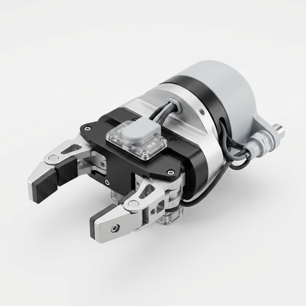
EOAT Machining Tolerances and Surface Finishes: A Buyer's Guide
Use this EOAT machining buyer's guide to set practical tolerances, surface finishes, ISO 2768 notes, and RFQ checks before quoting custom tooling.
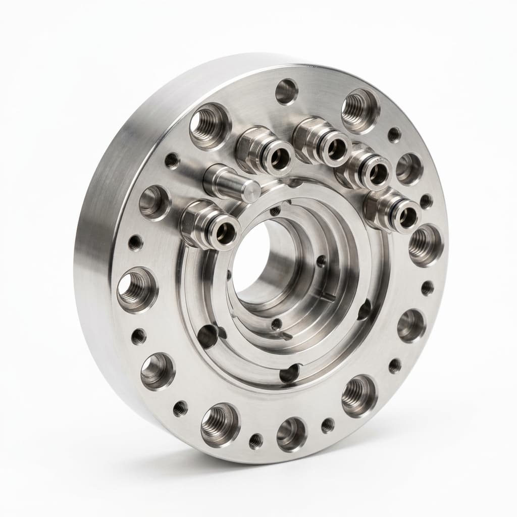
Robotic Automatic Tool Changers (ATC): Machining Tolerances and Procurement Specs for EOAT
Specify robotic Automatic Tool Changers for EOAT machining: repeatability, fail-safe locks, utility ports, payload moments, and supplier QA checks.